 Honda CBR650 - Service manual > Battery/charging system
Service information
GENERAL
WARNING
- The battery gives off explosive gases; keep sparks, flames and cigarettes away. Provide adequate ventilation when charging.
- The battery contains sulfuric acid (electrolyte). Contact with
skin or eyes may cause severe burns. Wear protective clothing and a face
shield.
- If electrolyte gets on your skin, flush with water.
- If electrolyte gets in your eyes, flush with water for at least 15 minutes and call a physician immediately.
- Electrolyte is poisonous.
- If swallowed, drink large quantities of water or milk and call your local Poison Control Center or a physician immediately.
NOTICE
- Always turn OFF the ignition switch before disconnecting any electrical component.
- Some electrical components may be damaged if terminals or connectors are connected or disconnected while the ignition switch is ON and current is present.
- For extended storage, remove the battery, give it a full charge, and store it in a cool, dry space. For maximum service life, charge the stored battery every 2 weeks.
- For a battery remaining in a stored motorcycle, disconnect the negative battery cable from the battery terminal.
- The maintenance free battery must be replaced when it reaches the end of its service life.
- The battery can be damaged if overcharged or undercharged, or if left to discharge for a long period. These same conditions contribute to shortening the "life span" of the battery. Even under normal use, the performance of the battery deteriorates after 2 - 3 years.
- Battery voltage may recover after battery charging, but under heavy load,
battery voltage will drop quickly and eventually die out.
For this reason, the charging system is often suspected as the problem. Battery overcharge often results from problems in the battery itself, which may appear to be an overcharging symptom. If one of the battery cells is shorted and battery voltage does not increase, the regulator/rectifier supplies excess voltage to the battery. Under these conditions, the electrolyte level goes down quickly.
- Before troubleshooting the charging system, check for proper use and maintenance of the battery. Check if the battery is frequently under heavy load, such as having the headlight and tail light ON for long periods of time without riding the motorcycle.
- The battery will self-discharge when the motorcycle is not in use. For this reason, charge the battery every 2 weeks to prevent sulfation from occurring.
- When checking the charging system, always follow the steps in the troubleshooting flow chart.
- For alternator service.
BATTERY CHARGING
- Turn power ON/OFF at the charger, not at the battery terminal.
- For battery charging, do not exceed the charging current and time specified on the battery. Using excessive current or extending the charging time may damage the battery.
- Quick charging should only be done in an emergency; slow charging is preferred.
BATTERY TESTING
Refer to the instruction of the Operation Manual for the recommended battery tester for details about battery testing. The recommended battery tester puts a "load" on the battery so the actual battery condition can be measured.
RECOMMENDED BATTERY TESTER: BM-210 or BATTERY MATE or equivalent
Troubleshooting
Battery is damaged or weak
1. Battery Test
Remove the battery.
Check the battery condition using the recommended battery tester.
RECOMMENDED BATTERY TESTER: BM-210 or BATTERY MATE or equivalent
Is the battery in good condition?
YES - GO TO STEP 2.
NO - Faulty battery
2. Current Leakage Test
Install the battery.
Check the battery current leakage using a digital multimeter.
Is the current leakage below 0.24 mA?
YES - GO TO STEP 4.
NO - GO TO STEP 3.
3. Current Leakage Test with Regulator/rectifier Connector Disconnected
Disconnect the regulator/rectifier 3P (Black) connector.
Recheck the battery current leakage.
Is the current leakage below 0.24 mA?
YES - Faulty regulator/rectifier
NO -
- Shorted wire harness
- Faulty ignition switch
4. Charging Voltage Inspection
Measure and record the battery voltage using a digital multimeter.
Start the engine.
Measure the charging voltage.
Compare the measurements to the results of the following calculation.
STANDARD:
Measured BV < Measured CV < 15.5 V
- BV = Battery Voltage
- CV = Charging Voltage
Do the battery and charging voltages satisfy the calculation?
YES - Faulty battery
NO - GO TO STEP 5.
5. Alternator Charging Coil Inspection
Check the alternator charging coil.
Is the alternator charging coil resistance within 0.1 - 1.0 Ω (20ºC/68ºF)?
YES - GO TO STEP 6.
NO - Faulty charging coil
6. Regulator/rectifier Wire Harness Inspection
Check the regulator/rectifier wire harness.
Are the results of checked voltage and continuity correct?
YES - Faulty regulator/rectifier
NO -
- Open circuit in related wire
- Loose or poor contacts of related terminal
- Shorted wire harness
System location
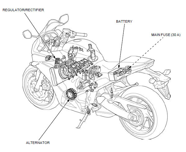
- REGULATOR/RECTIFIER
- BATTERY
- MAIN FUSE (30 A)
- ALTERNATOR
System diagram
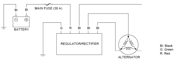
Battery
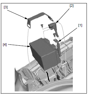
REMOVAL/INSTALLATION
Remove the seat.
Turn the ignition switch OFF.
Disconnect the negative (-) cable [1] first and then disconnect the positive (+) cable [2] by removing the terminal bolts.
Remove the rubber strap [3] and the battery [4].
Installation is in the reverse order of removal.
NOTE
- Connect the positive (+) cable first, then connect the negative (-) cable.
- For digital clock setting procedure.
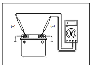
VOLTAGE INSPECTION
Remove the seat.
Measure the battery voltage using a digital multimeter.
VOLTAGE (20ºC/68ºF):
Fully charged: 13.0 - 13.2 V
Needs charging: Below 12.4 V
NOTE:
- When measuring the battery voltage after charging, leave it for least 30 minutes, or the accurate results cannot be obtained because the battery voltage fluctuates just after charging.
Charging system inspection
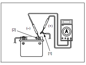
CURRENT LEAKAGE TEST
Remove the seat.
Turn the ignition switch OFF.
Remove the terminal bolt and disconnect the negative (-) cable [1] from the battery.
Connect the ammeter (+) probe to the negative (-) cable and ammeter (-) probe to the battery negative (-) terminal [2].
With the ignition switch turned OFF, check for current leakage.
NOTE:
- When measuring current using a tester, set it to a high range, and then bring the range down to an appropriate level. Current flow higher than the range selected may blow the fuse in the tester.
- While measuring current, do not turn the ignition switch ON. A sudden surge of current may blow the fuse in the tester.
SPECIFIED CURRENT LEAKAGE: 0.24 mA max.
If current leakage exceeds the specified value, a shorted circuit is likely.
Locate the short by disconnecting connections one by one and measuring the current.
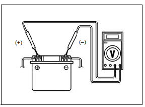
CHARGING VOLTAGE INSPECTION
NOTE:
- Be sure the battery is in good condition before performing this test.
- Do not disconnect the battery or any cable in the charging system without first switching off the ignition switch. Failure to follow this precaution can damage the tester or electrical components.
Warm up the engine to normal operating temperature.
Stop the engine.
Remove the seat.
To prevent a short, make absolutely certain which are the positive (+) and negative (-) terminals or cables.
Connect the multimeter between the battery positive (+) terminal and negative (-) terminal of the battery.
With the headlight on high beam, restart the engine.
Measure the voltage on the multimeter when the engine runs at 5,000 min-1 (rpm).
STANDARD:
Measured BV < Measured CV < 15.5 V
- BV = Battery Voltage
- CV = Charging Voltage
Alternator charging coil
INSPECTION
Remove the following:
- Left middle cowl (CBR650F/FA)
- Left tank shroud A (CB650F/FA)
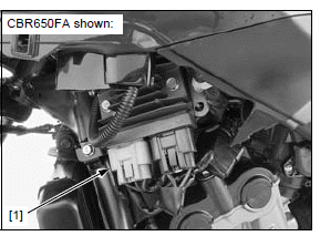
Disconnect the alternator 3P (Gray) connector [1] from the regulator/rectifier.
Check the connector for loose contacts or corroded terminals.
Measure the resistance between the Black wire terminals of the alternator side 3P (Gray) connector.
STANDARD: 0.1 - 1.0 Ω (20ºC/68ºF)
Check for continuity between each wire terminal of the alternator side 3P (Gray) connector and ground.
There should be no continuity.
Replace the alternator stator if the resistance is out of specification, or if any wire has continuity to ground.
For alternator stator replacement.
Regulator/rectifier
WIRE HARNESS INSPECTION
Remove the following:
- Left middle cowl (CBR650F/FA)
- Left tank shroud A (CB650F/FA)
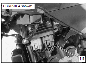
Disconnect the regulator/rectifier 3P (Black) connector [1].
Check the connector for loose contacts or corroded terminals.
Check the following at the wire harness side 3P (Black) connector.
- Battery Line: Measure the voltage between the Red wire terminal (+) and
ground (-).
There should be battery voltage at all times.
- Ground Line: Check for continuity between the Green wire terminal and
ground.
There should be continuity at all times.
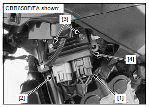
REMOVAL/INSTALLATION
Remove the following:
- Left middle cowl (CBR650F/FA)
- Left tank shroud B (CB650F/FA)
Disconnect the regulator/rectifier 3P (Black) [1] and alternator 3P (Gray) [2] connectors.
Remove the two bolts [3] and regulator/rectifier [4].
Installation is in the reverse order of removal.

 Rider's Manual BMW R 1250 GS GSA
 Owner's Manual Harley-Davidson Sportster XL1200X Forty-Eight
 Owner's Manual Honda CBR650R
 Service manual Honda CBR650
 Owner's Manual Honda PCX125
 Owner's Manual Kawasaki Z1000SX
 Service manual Kawasaki Z1000SX
 Owner's Manual Lexmoto Echo
 Owner's Manual Royal Enfield Interceptor 650
 Service manual Royal Enfield Interceptor 650
 Owner's Manual Yamaha MT-07