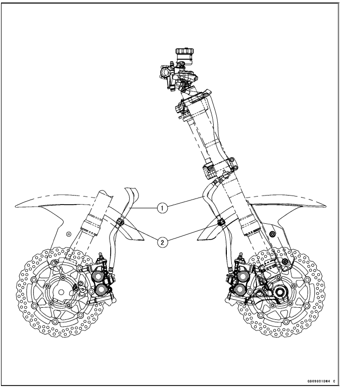
 Kawasaki Z1000SX - Service manual > Cable, Wire, and Hose Routing
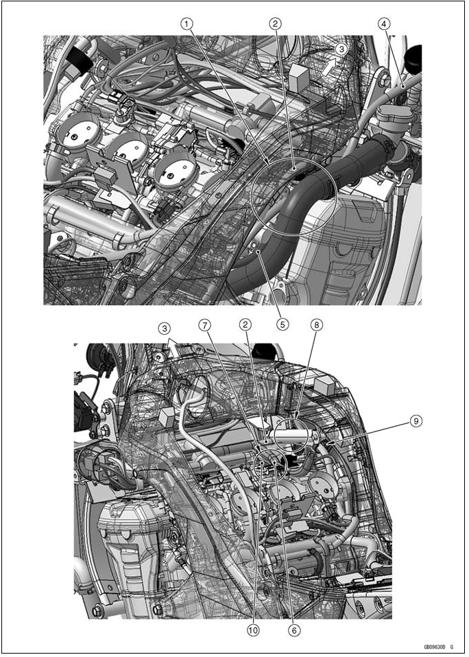
Appendix / Cable, Wire, and Hose Routing
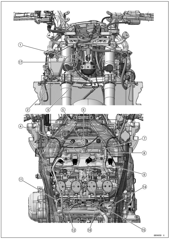
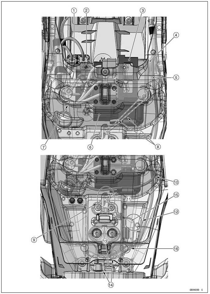
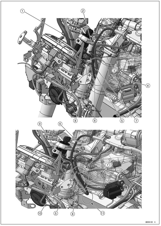
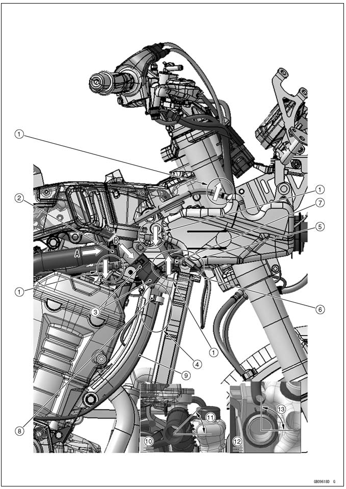
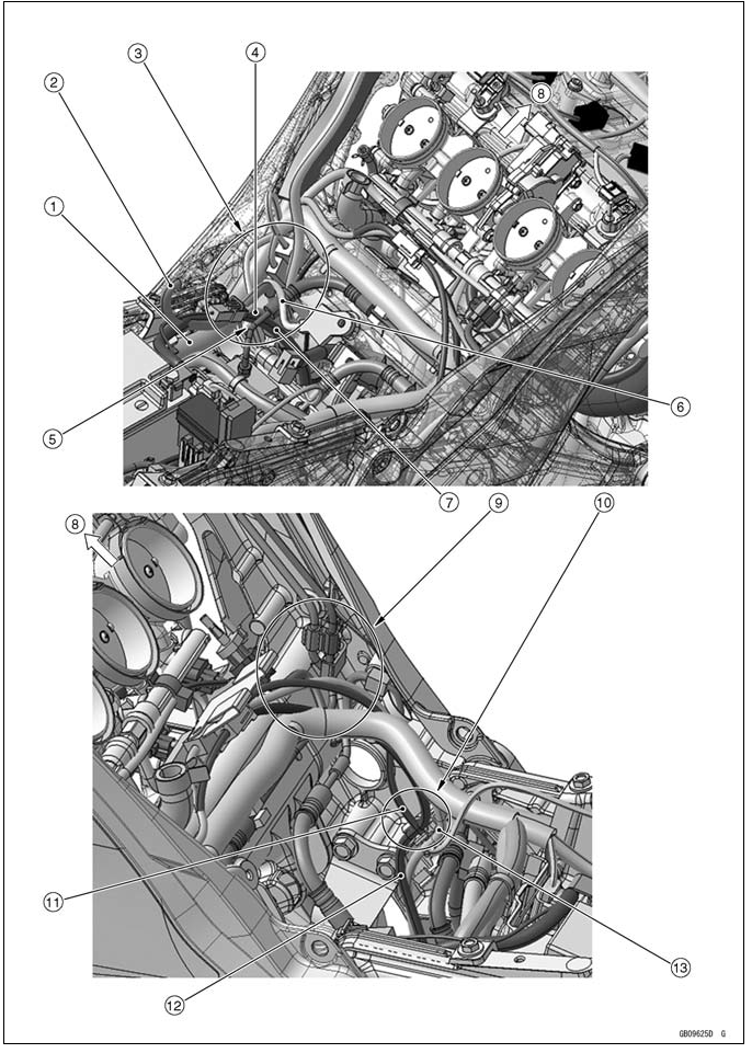
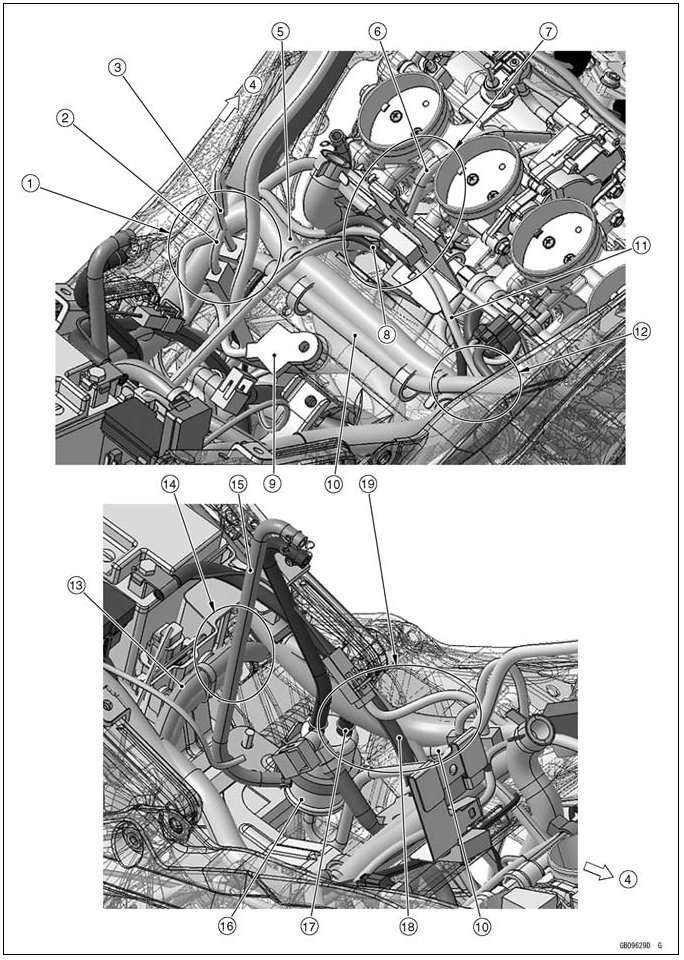
- Headlight Lead
- Run the brake hose to the rear side of the headlight lead.
- Brake Hose
- Run the front right turn signal light lead through the air switching valve. And run to the rear side of the light switch housing.
- Air Switching Valve Clamp
- Air Switching Valve
- Air Switching Valve Hose
- Run the air switching valve hose to the upside of the stick coil lead.
- Stick Coil Lead
- Run the injector lead to the front side of the breather hose.
- Injector Lead
- Breather Hose
- Hold the injector lead with clamp
- Run the intake air temperature sensor to the upside of the crankshaft sensor lead.
- Intake Air Temperature Sensor Lead
- Crankshaft Sensor Lead
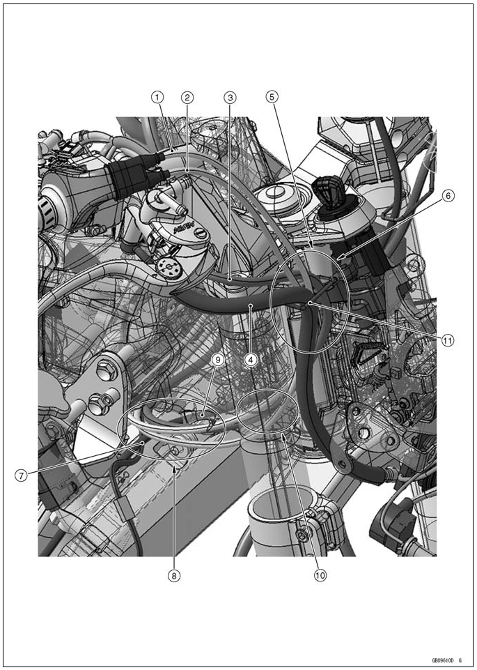
- Connect the horn lead connectors so that the horn lead comes upside.
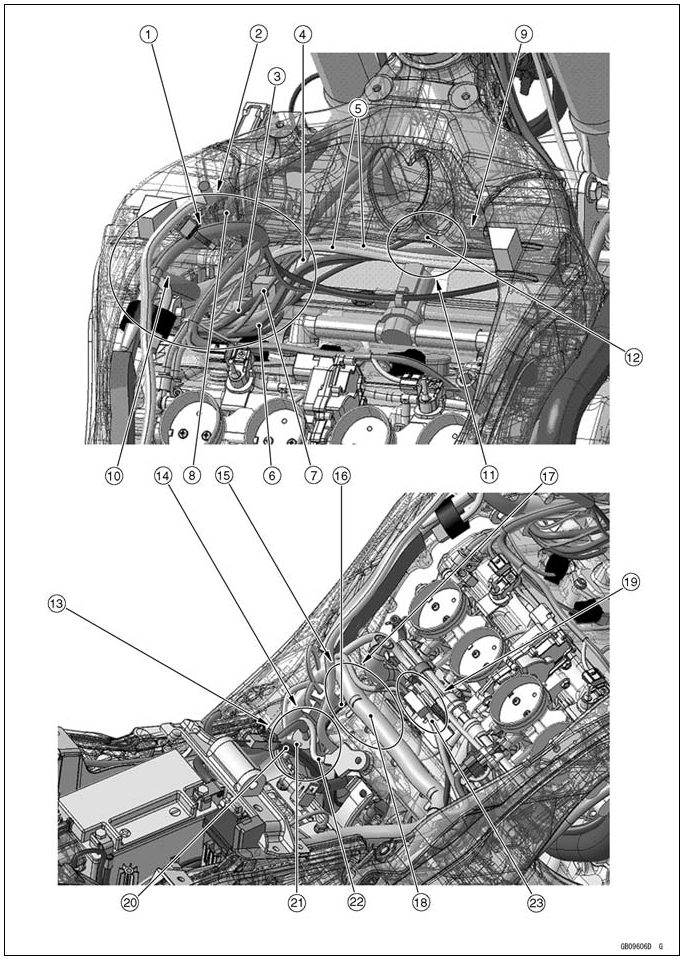
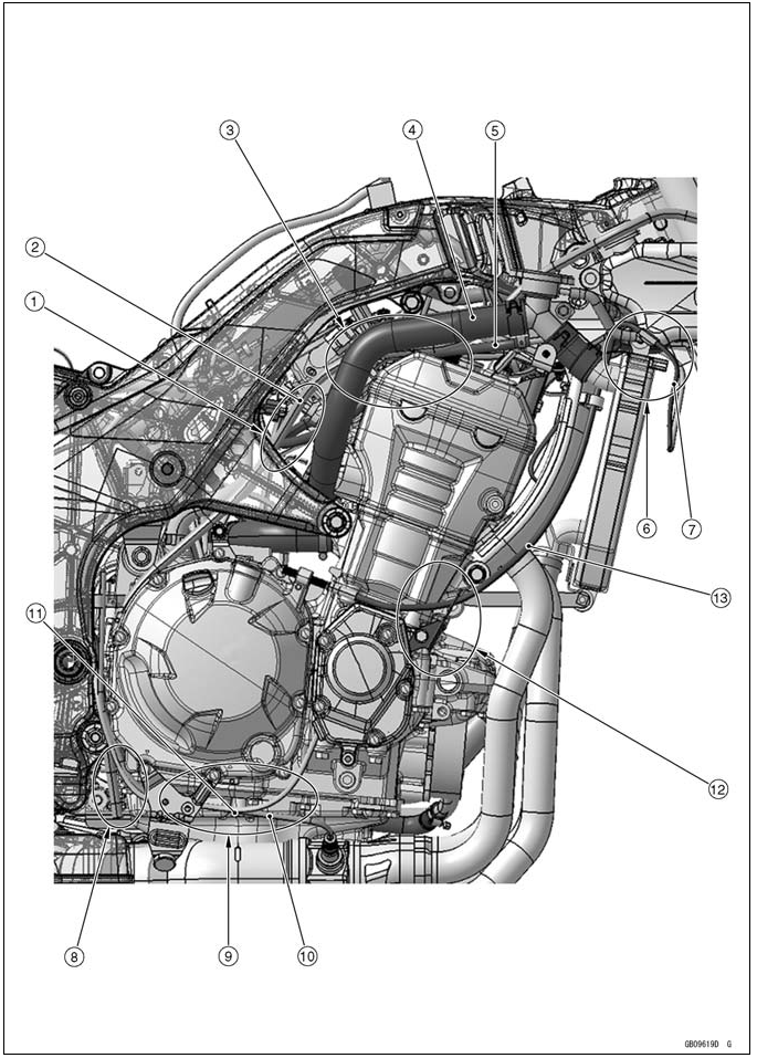
- Insert the clamp on the main harness to the rib of the frame as shown.
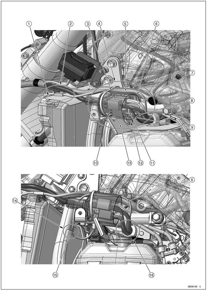
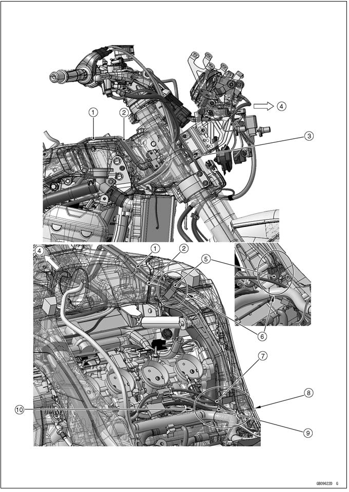
- Run the headlight lead, right and left light switch housing lead, ignition switch lead, immobilizer amplifier lead (equipped models) and radiator fan motor lead to the front side of engine mount bracket, right turn signal light lead and air switching valve, and run them under the throttle cable and outside of frame.
- Left Switch Housing Lead
- Ignition Switch Lead
- Throttle Cables
- Right Switch Housing Lead
- Immobilizer Amplifier Lead
- Headlight Lead
- Run the clutch cable under the other lead and front side of radiator.
- Run the main harness to the outside of the between engine mount bracket and frame.
- Run the radiator fan motor lead, right switch housing and throttle cable in order from the frame.
- Radiator Fan Motor Lead
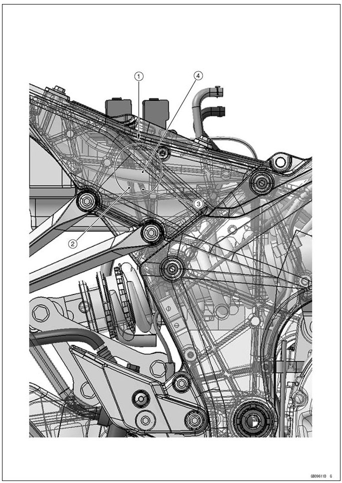
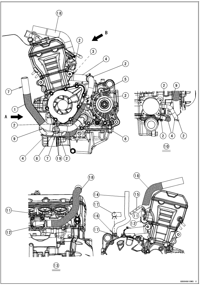
- Run the starter motor cable (+) to the upside of the battery negative (-) cable.
- Run the frame ground lead to the front side of the starter motor cable and battery negative (-) cable.
- Run the alternator lead to the under the main harness.
- Alternator Lead
- Run the alternator lead and crankshaft sensor lead to the rear side of breather hose.
- Main Harness
- Hold the alternator lead and crankshaft sensor lead with clamp.
- Battery Negative (-) Cable
- Starter Motor (+) Cable
- Frame Ground Lead
- Crankshaft Sensor Lead
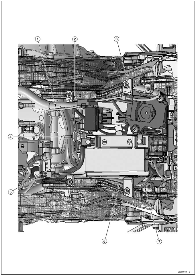
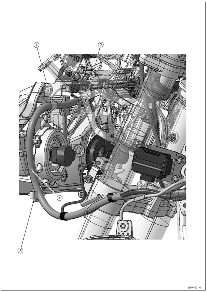
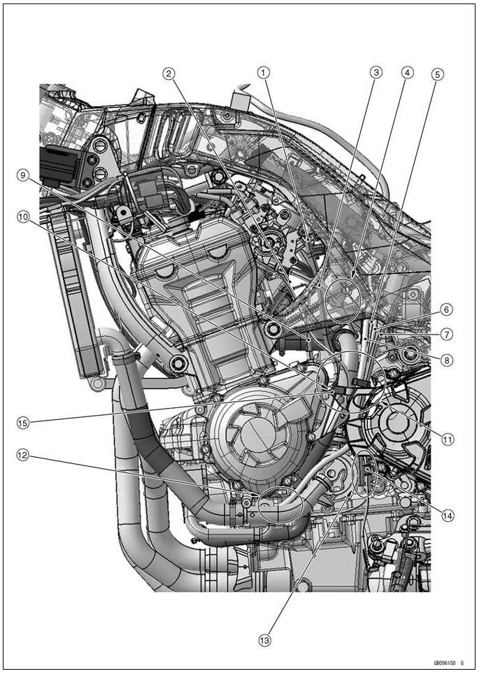
- Run the fuel pump lead to the upside of the exhaust butterfly valve cables, to the outside of the fuse box, and to under the fuel tank bracket.
- Run the rear of main harness to inside of the battery case, to underside of the fuel pump lead, to rear of the battery case mounting and to the outside of the battery case as shown.
- Hold the fuel pump lead (main harness side) with the clamp.
- Hold the main harness with the clamp.
- Run the regulator/rectifier harness to the under the battery case.
- Run the starter motor cable to the upside of the main harness.
- Run the starter motor cable to between the main relay and battery, and to inside of the starter motor cable.
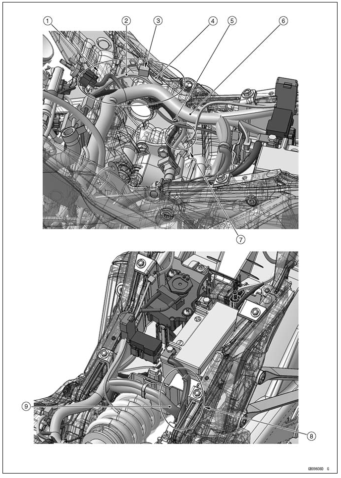
- Run the oxygen sensor lead (equipped models), crankshaft sensor lead and rear brake light switch lead to the outside of main harness.
- Crankshaft Sensor Lead
- Hold the rear brake light switch connector with the clamp.
- Rear Brake Light Switch Lead
- Oxygen Sensor Lead
- Main Harness
- Insert the clamps to the ribs of the inside of the frame, hold the oxygen sensor lead and crankshaft sensor lead.
- Run the regulator/rectifier harness from the cutout on the battery case to under side of the battery case.
- Regulator/Rectifier Harness
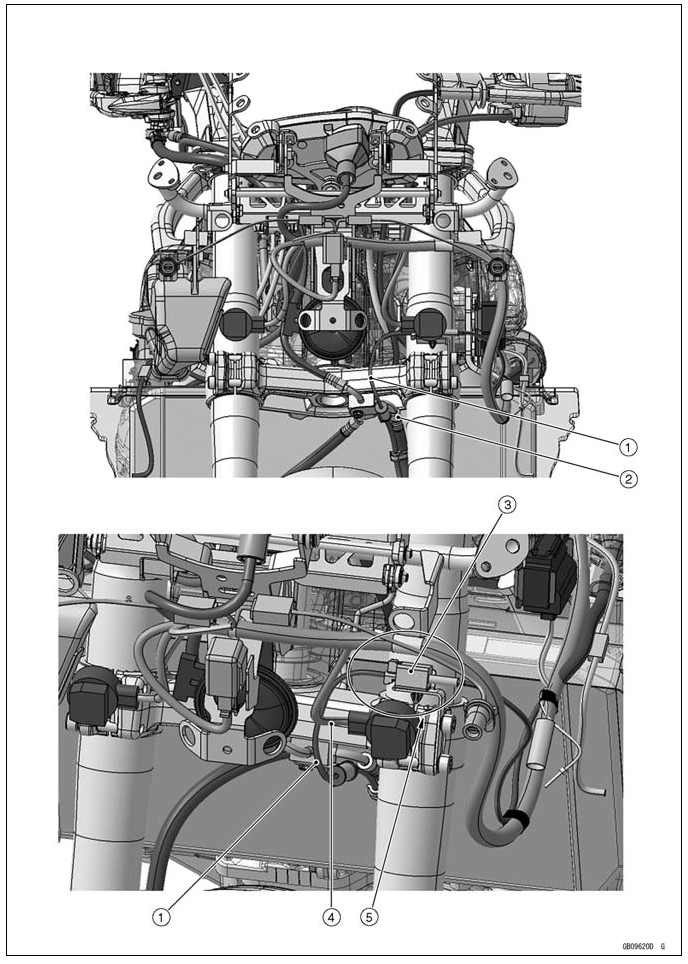
- Kawasaki Diagnostic System Connector
- ABS Self-diagnosis Connector (ABS Equipped Models)
- Relay Box
- Rear Left Turn Signal Light Lead
- Rear Right Turn Signal Light Lead
- ECU
- Run the leads to forward of the rear fender wall connect them.
- Run the turn signal light leads to the inside of ECU rib under the ECU and connect them.
- Run the right and left turn signal light leads to forward of the rear frame wall and connect them.
- Run the seat lock cable to front side of the frame wall and upside of the turn signal light lead and license plate light lead.
- Rear Left and Right Turn Signal Light Lead
- Run the license plate light lead to right side of the frame and connect them at position as shown.
- Tail/Brake Light (LED) Lead
- Run the licence plate light lead and tail/brake light (LED) lead reward to under of the rear frame after connected. Be careful not to pinch the leads with rear fender.
- License Plate Light Lead
- Run the licence plate light lead (main harness side) and tail/brake light (LED) lead (main harness side) reward to under of the rear flame (for prevention to pinch the leads with rear fender).
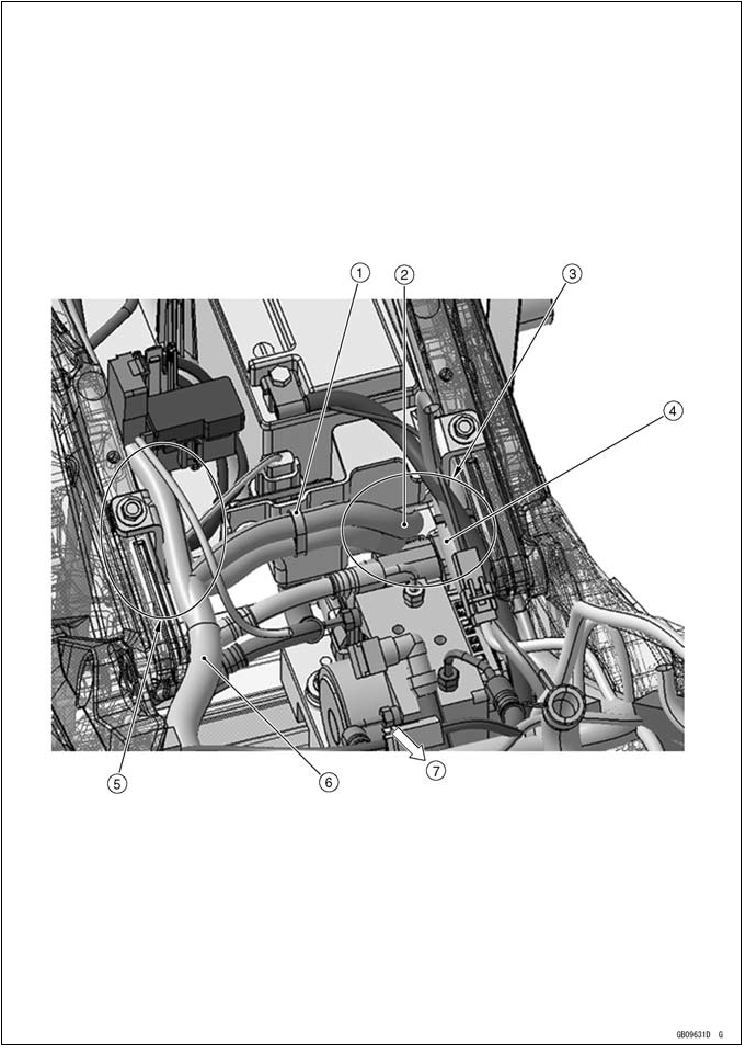
- Throttle Cable (Accelerator)
- Throttle Cable (Decelerator)
- Right Switch Housing Lead
- Brake Hose
- Clamp the brake hose, throttle cable (decelerator), throttle cable (accelerator) and right switch housing lead in order from the outside of frame.
- Run the brake hose comes to the most front side of the other lead. Run the right switch housing lead comes to the most rear side of the other lead.
- Front Right Turn Signal Light Lead
- Run the throttle cables, clutch cable, front turn signal light lead, right switch housing leads through this point to the inside of the frame.
- Clutch Cable
- Run the throttle cables and right switch housing leads through the inside of front fork.
- Clamp
- Run the exhaust butterfly valve cables to inside of the main harness.
- Exhaust Butterfly Valve Close Cable
- Exhaust Butterfly Valve Open Cable
- Main Harness
- Bend the clamp upward to secure the harness at the portion of the taped.
- Install the main harness clamp at the headlight bracket.
- Bend the clamp reward to inside to secure the harness at the portion of the taped.
- Main Harness
- Clamp
- Run the clutch cable and left switch housing lead in order from the inside of clamp.
- Clamp
- Run the left switch housing leads, ignition switch lead, immobilizer antenna lead (equipped models), and clutch cables to the inside of the front fork.
- Immobilizer Antenna Lead
- Clutch Cable
- Left Switch Housing Lead
- Ignition Switch Lead
- Run the ignition switch lead and immobilizer antenna lead inside of clamp.
- Clamp
- Run the clutch cable outside through the lower side of the radiator mounting position, and to the under of the other leads.
- Clamp
- Run the ignition switch lead, immobilizer antenna lead and left switch housing lead to the inside of the clamp.
- Insert the hole on the engine top heat protector into the slit on the radiator side pad.
- Connect the left turn signal light lead at the rear of radiator side pad, and push its connector into the cutout on the pad.
- Band
- Cover the right switch housing lead, ignition switch lead, immobilizer antenna lead (equipped models) and radiator fan motor lead with the rubber cover, and tie the rubber cover and main harness and neutral switch/oil pressure switch with the band then secure them to the heat insulation plate. Cut the band excess length after tying them.
- Main Harness
- Neutral Switch/Oil Pressure Switch Lead
- Ignition Switch Lead
- Right Switch Housing Lad
- Radiator Fan Motor Lead
- Rubber Cover
- Immobilizer Antenna Lead
- Hold the engine top heat protector to the heat insulation plate with the rivets from the front side (the right side is same as the left side).
- Heat Insulator
- Run the neutral switch/oil pressure switch lead to inside of rubber cover and connect them. Then hold the neutral switch/oil pressure switch lead with clamp on the engine bracket.
- Clamp
- Hold the neutral switch/oil pressure switch lead with clamp on the bracket.
- Air Cleaner Drain Hose
- Neutral Switch/Oil Pressure Switch Lead
- Idle Adjusting Screw
- Run the starter motor cable to the upside of the idle adjusting screw.
- Sidestand Switch Lead
- Speed Sensor Lead
- Fuel Tank Breather Hose (other than CAL and SEA-B1 models)
- Fuel Tank Drain Hose
- Starter Motor Cable
- Run the alternator lead to the outside of air cleaner drain hose and inside of neutral switch/oil pressure switch lead.
- Run the speed sensor lead and sidestand switch lead to the inside of the breather hose and fuel tank drain hose (other than CAL and SEA-B1 models).
- Run the end of fuel tank drain hose is as shown.
- Hold the sidestand switch lead with the clamp.
- Clamp
- Alternator Lead
- Air Cleaner Drain Hose
- Idle Adjusting Screw
- Run the idle adjusting screw to the under of the starter motor cable, outside of the air cleaner drain hose.
- Starter Motor Cable
- Run the fuel hose, starter motor cable, and alternator lead in order from the inside of the frame.
- Fuel Hose
- Alternator Lead
- Fuel Tank Drain Hose
- Sidestand Switch Lead
- Fuel Tank Breather Hose (other than CAL and SEA-B1 Models)
- Run the fuel tank breather hose (other than CAL and SEA-B1 models), sidestand switch lead and fuel tank drain hose to the inside of the chain cover.
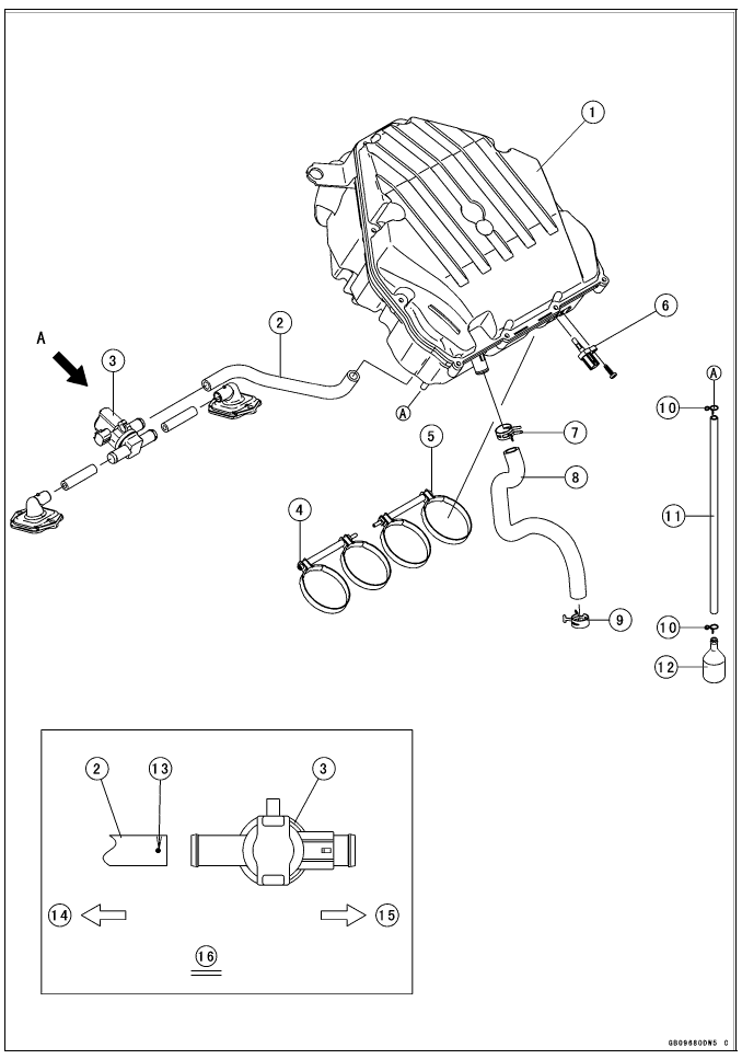
- Air Cleaner Housing
- Air Switching Valve Hose
- Air Switching Valve
- Tighten the clamp bolt from left side.
- Tighten the clamp bolt from right side.
- Intake Air Temperature Sensor
- Install the clamp so that knob of the clamp faces rear side of the frame as shown.
- Breather Hose
- Clamp
- Clamps
- Air Cleaner Drain Hose
- Catch Tank
- White Paint Mark
- Right
- Left
- Viewed from A
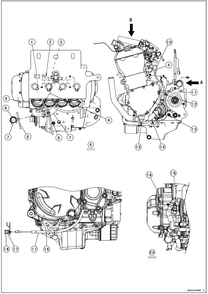
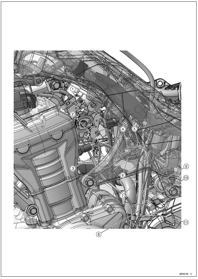
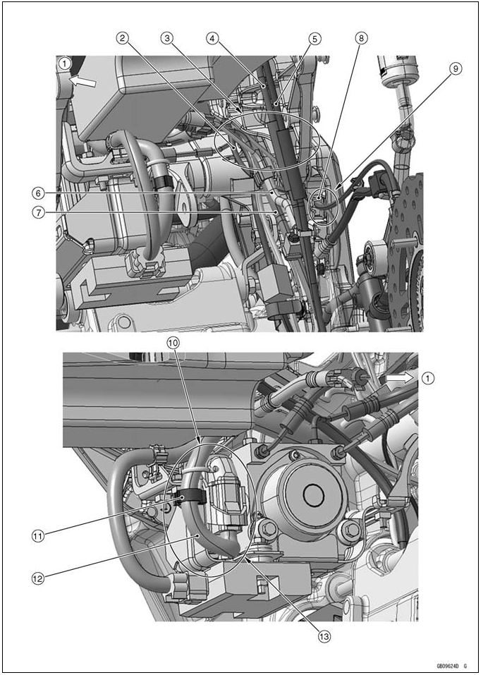
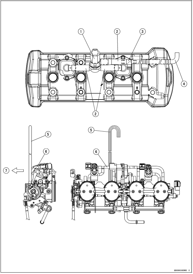
- Insert the subharness connector to the clamp on the air suction valve cover.
- Run the subharness under the hose.
- Hose
- Subharness
- Run the subharness between the #1 and #2 throttle body holders so as not to pinch the lead with the throttle body assy.
- Install the clamp as shown in the direction.
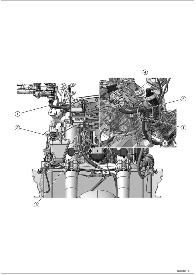
- Water Hose
- Starter Motor Cable
- Viewed from B
- Water Temperature Sensor Lead
- Hold the neutral switch/oil pressure switch lead with the clamp at the upside of the separate pipe of the water pipe.
- Run the neutral switch/oil pressure switch lead with the clamp at the rear side of the separate pipe of the water pipe.
- Connect the neutral switch lead to the neutral switch. Do not stretch the lead after connected.
- Run the oil pressure switch lead to the inside of the water pipe.
- Cover the oil pressure switch with the switch cover.
- Hold the crankshaft sensor lead with the clamp.
- Crankshaft Sensor Lead
- Water pipe
- Run the alternator lead between the crankcase and water pipe.
- Viewed from A
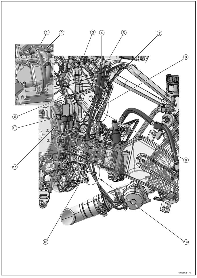
- Regulator/Rectifier Harness
- Hold the regulator/rectifier harness with clamp.
- Rear Brake Light Switch Lead
- Exhaust Butterfly Valve Open Cable
- Exhaust Butterfly Valve Close Cable
- Oxygen Sensor Lead (Equipped Models)
- Run the rear brake light switch lead through the clamp to outside of exhaust butterfly valve cables.
- Run the exhaust butterfly valve open cable and close cable through the clamp in order from the front.
- Clamp (for Exhaust Butterfly Valve Cables)
- Clamp (for Oxygen Sensor Lead and Crankshaft Sensor Lead)
- Bend the clamp reaward to secure the oxygen sensor lead and crankshaft sensor lead.
- Crankshaft Sensor Lead
- Clamp (for Exhaust Butterfly Valve Cable)
- Run the exhaust butterfly valve open cable and close cable through the clamp in order from the front.
- Install the clamps as shown in the direction.
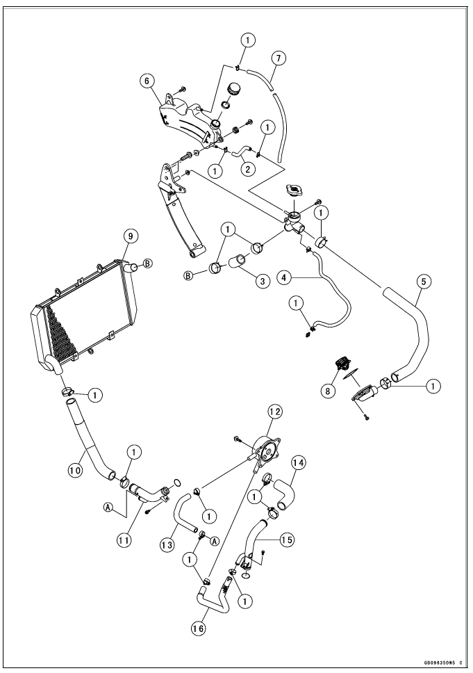
- Reserve Tank Hose
- Radiator Hose
- Water Hose
- Water Hose
- Reserve Tank
- Reserve Tank Overflow Hose
- Thermostat
- Radiator
- Radiator Hose
- Water Pipe
- Oil Cooler
- Water Hose
- Water Hose
- Water Pipe
- Water Hose
- Install the clamps so that its opening facing the direction indicated with arrow.
- Clamp (for Water Hose)
- Clamp (for Radiator Hose)
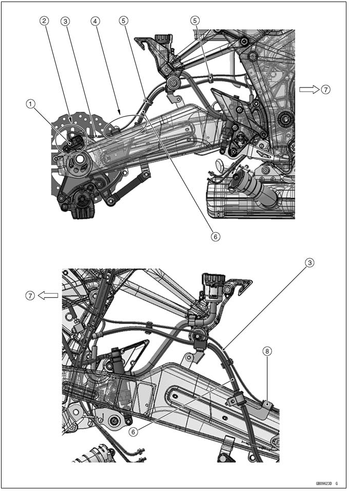
- Hold the clutch cable with clamp.
- Run the front right turn signal light lead to the upside of the reserve tank overflow hose.
- Front Turn Signal Light Lead
- Reserve Tank Overflow Hose
- Clamp (for Clutch Cable)
- Clutch Cable
- Viewed From A
- About 45º
- Viewed From B
- About 90º
- Run the reserve tank overflow hose to the inside of the frame.
- Reserve Tank Overflow Hose
- Run the water hose, reserve tank overflow hose, water hose in order the outside of frame.
- Water Hose
- Water Hose
- Connect the right turn signal light lead at the rear of radiator side pad, and push its connector into the cutout on the pad.
- Right Turn Signal Light Lead
- Run the reserve tank overflow hose to behind of the adjusting bolt, and between the adjusting bolt and frame, and directs it to underside of the frame.
- Hold the oxygen sensor lead (equipped models) and crankshaft sensor lead with clamp.
- Oxygen Sensor Lead
- Crankshaft Sensor Lead
- Run the clutch cable to front of engine bracket through the clamp on the front of the crankshaft sensor cover and inside of upper radiator hose.
- Clutch Cable
- Radiator Hose
- Install the clamps as shown, noting its screw head direction.
- White Paint Mark (Install the water hose so that the white paint mark faces upside of the engine.)
- Water Hose
- White Paint Mark (Install the water hose so that the white paint mark faces outside of the engine.)
- Water Hose
- Straight Side
- Install the radiator hose until the rised portion of the water pipe.
- Curve Side
- Viewed from A
- Install the clamp so that the tab of the clamp faces rear side of the engine.
- Install the clamp at the thermostat housing so that the tab of the clamp faces rear side of the engine.
- Viewed from B
- Breather Hose
- Water Hose
- White Paint Mark
- Install the clamp so that the tab of the clamp faces right side of the engine.
- Water Hose
- White Paint Mark (Install the water hose and water pipe so that the white paint mark faces outside of the engine.)
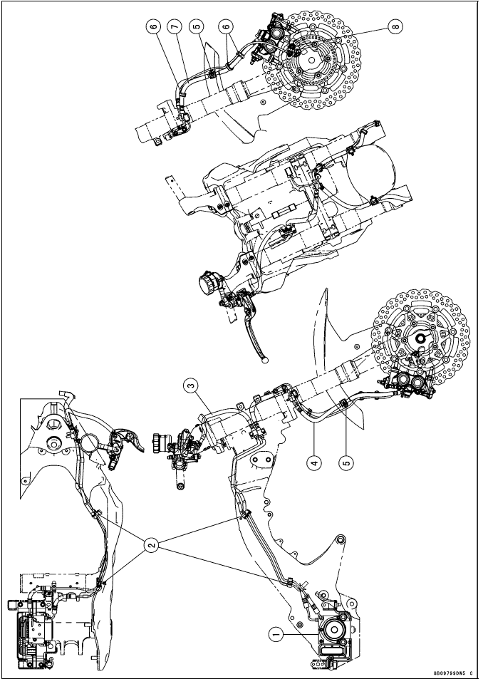
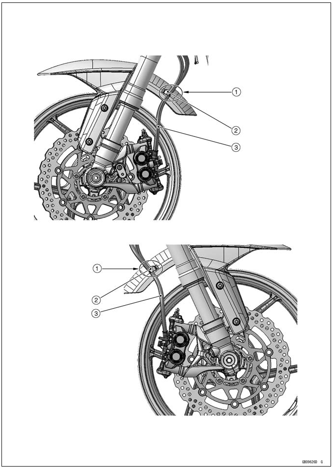
ABS Equipped Models
- Front Wheel Rotation Sensor Lead
- Clamps (for Brake Hose and Front Wheel Rotation Sensor Lead)
- Front Wheel Rotation Sensor Connector
- Headlight Lead
- Run the front wheel rotation sensor lead to the outside of the headlight lead, and connect the front wheel rotation sensor connector at the front fork bracket.
ABS Equipped Models
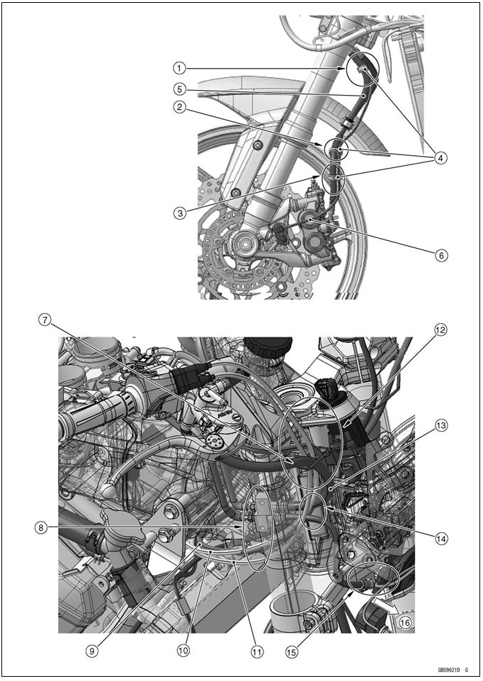
- Hold the brake hose inside the front wheel rotation sensor lead with clamp. Install the clamp with its closed side facing forward.
- Hold the brake hose at the rubber portions with the clamp.
- Run the front wheel rotation sensor lead to the rear side of the brake hose. Install the clamp with its closed side facing outside.
- Clamp (for Front Wheel Rotation Sensor Lead and Brake Hose)
- Brake Hose
- Front Wheel Rotation Sensor Lead
- Run the brake hose to the most forward side, and the right switch housing lead to the most behind of the other leads and run them into the clamp.
- Run the brake hose, right switch housing lead, throttle cable (accelerator) and throttle cable (decelerator) in order from the outside of frame.
- Right Switch Housing Lead
- Throttle Cable (Accelerator)
- Throttle Cable (Decelerator)
- Run the brake hose, throttle cable (decelerator), throttle cable (accelerator) and right switch housing lead in order from the outside of frame.
- Brake Hose
- Run the right switch housing lead to the inside of brake hose.
- Run the brake hose to the most outside of the other lead.
- Front
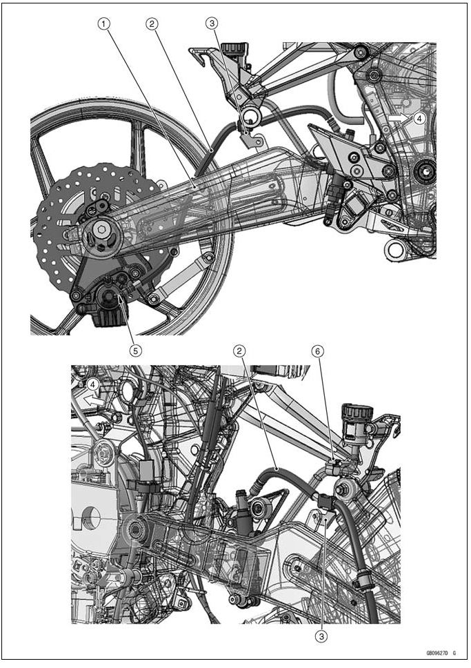
ABS Equipped Models
- Brake Pipe
- Brake Pipe
- Brake Hose
- Front
- Clamp (Hold the brake pipes)
- Hold the brake pipes at the rubber portions with the clamps.
- Rear Wheel Rotation Sensor Lead
- Run the rear wheel rotation sensor lead to the outside of the main harness and upper the intake air temperature sensor lead.
- Intake Air Temperature Sensor Lead
- Run the brake pipes under the harnesses.
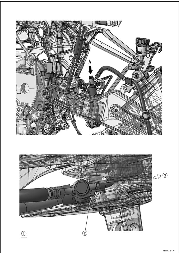
ABS Equipped Models
- Rear Wheel Rotation Sensor
- Run the rear wheel rotation sensor lead into the clamp.
- Rear Wheel Rotation Sensor Lead
- Run the rear wheel rotation sensor lead upper the brake hose, and hold the brake hose at the attaching mark with the clamp.
- Clamp (for Brake Hose and Rear Wheel Rotation Sensor Lead)
- Brake Hose
- Front
- Clamp (for Rear Wheel Rotation Sensor Lead)
ABS Equipped Models
- Front
- Rear Wheel Rotation Sensor Lead
- Run the exhaust butterfly valve close cable, exhaust butterfly valve open cable, brake hose, brake light switch lead, rear wheel rotation sensor lead in order from the inside of frame.
- Exhaust Butterfly Valve Open Cable
- Exhaust Butterfly Valve Close Cable
- Brake Hose
- Brake Hose
- Clamp
- Hold the brake light switch lead and rear wheel rotation sensor lead with clamp.
- Run the ABS hydraulic unit harness under the battery case so that the harness has no play in this position (Run the under the battery case).
- Clamp (for ABS Hydraulic Unit Harness)
- ABS Hydraulic Unit Harness
- Run the ABS hydraulic unit harness as shown.
ABS Equipped Models
- Air Cleaner Drain Hose
- Breather Hose
- Run the breather hose and air cleaner drain hose through the front side of frame ground lead and outside of the starter motor cable.
- Starter motor (+) Cable
- Run the brake pipe through the inside of the starter motor (+) cable and battery negative (-) cable and under the frame ground lead.
- Frame Ground Lead
- Battery Negative (-) Cable
- Front
- Run the brake hoses under the other harnesses.
- Run the wheel rotation sensor lead and rear brake light switch lead to the outside of the oxygen sensor lead and crankshaft sensor lead.
- Wheel Rotation Sensor Lead
- Oxygen Sensor Lead
- Crankshaft Sensor Lead
ABS Equipped Models
- Clamp (Hold the each harness.)
- Regulator/Rectifier Harness
- Run the regulator/rectifier harness from the cutout on the battery case to underside of the battery case.
- ABS Hydraulic Unit Harness
- Run the rear of main harness to upside of the battery case, to rear of the battery case mount portion, and to outside of the battery case.
- Main Harness
- Front
ABS Equipped Models
- ABS Hydraulic Unit
- Clamps
- Brake Hose (between Front Master Cylinder and ABS Hydraulic Unit)
- Brake Hose (between ABS Hydraulic Unit and Right Front Caliper)
- Clamp (Hold the grommet of the brake hose only. For ZX1000HB late model -, face the lock portion of the clamp backward.)
- Hold the front brake hose and the front wheel rotation sensor lead with the clamp at the white painted portion of the sensor lead.
- Brake Hose (between ABS Hydraulic Unit and Left Front Caliper)
- Front Wheel Rotation Sensor
ABS Equipped Models

- ABS Hydraulic Unit
- Clamps
- Brake Hose (between Rear Master Cylinder and ABS Hydraulic Unit)
- Brake Hose (between ABS Hydraulic Unit and Rear Caliper)
- Rear Wheel Rotation Sensor
- Rear Wheel Rotation Sensor Lead
- Section A-A
- Section B-B
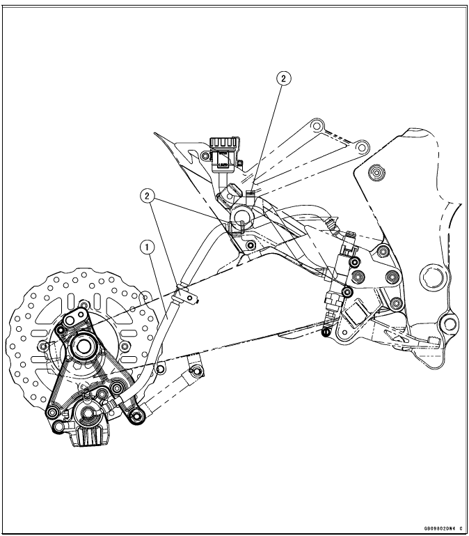
- Brake Hose
- Headlight Lead
- Run the brake hose to the rear side of the headlight lead.
- Run the brake hose to the most front side of the other leads and cables, and through it to the clamp.
- Clamp
- Front
- (ZX1000GB Early Model) Hold the brake hose with the clamp at the grommet
of the brake hose, and insert it to the front fender.
(ZX1000GB Late Model -) Hold the brake hose with the clamp at the grommet of the brake hose. Face the lock portion of the clamp backward. - Clamp (for Brake Hose)
- Brake Hose
- Clamp (for Brake Hose)
- Brake Hose
- Clamp (for Brake Hose)
- Front
- Fit the brake pipe to the stopper of the caliper as shown, and tighten the brake hose banjo bolt to the specified torque.
- Clamp (for Brake Hose)
- Viewed From A
- Fit the projection of the brake hose end to the stopper as shown, and tighten the brake hose banjo bolt to the specified torque.
- Front
- Brake Hoses
- Clamps (Hold the grommet of the brake hose only. For ZX1000GB late model -, face the lock portion of the clamp backward.)
- Brake Hose
- Clamps
CAL and SEA-B1 Models
- Run the purge hose to the inside of the sidestand switch lead and speed sensor lead, upside of the main harness and frame ground lead.
- Sidestand Switch Lead
- Speed Sensor Lead
- Front
- Main Harness
- Vacuum Hose (between Separator and Throttle Body)
- Run the vacuum hose to the under the delivery pipe of the throttle body assy. Crankshaft sensor lead and alternator lead. And run to the vacuum hose to upside of the main harness.
- Alternator Lead
- Frame Ground
- Purge Hose (between Canister and Fitting for Air Switching Valve)
- Crankshaft Sensor Lead
- Run the purge hose to the upside of the other lead.
- Regulator/Rectifier Harness
- Run the return hose to the front side of the regulator/rectifier harness.
- Return Hose (between Separator and Fuel Tank)
- Separator
- Breather Hose (between Separator and Canister)
- Battery Negative (-) Lead
- Run the Battery Negative (-) Lead to the upside of the breather hose and inside of the purge hose.
CAL and SEA-B1 Models
- Run the water hose, reserve tank overflow hose, purge hose in order from the outside of frame.
- Purge Hose (between Canister and Fitting for Air Switching Valve)
- Front
- Reserve Tank Overflow Hose
- Water Hose
- Air Switching Valve Hose (between Air Cleaner and Fitting for Air Switching Valve)
- Run the air switching valve hose to the upside of the stick coil lead.
- Run the purge hose under the engine mount bracket.
- Hold the water hose, purge hose in order the outside of frame with clamp.
- Stick Coil Lead
CAL and SEA-B1 Models
- Canister
- Install the canister hose clamps with its tabs facing upward.
- Main Relay Lead
- Run the breather hose and purge hose to the under the main relay lead.
- Breather Hose (between Canister and Separator)
- Run the breather hose under the purge hose.
- Run the breather hose and purge to the upside of the main harness and to the outside of the starter motor cable.
- Purge Hose (between Canister and Fitting for Air Switching Valve)
- Starter Motor (+) Cable
- Front
CAL and SEA-B1 Models
- Air Switching Valve
- Hoses
- Fitting
- Install the purge hose as shown in the direction.
- Run the vacuum hose to the front side of the vacuum hose.
- Vacuum Hose
- Front
See also:
 Kawasaki Z1000SX - Service manual > Troubleshooting Guide
NOTE Refer to the Fuel System chapter for most of DFI trouble shooting guide. This is not an exhaustive list, giving every possible cause for each problem listed. It is meant simply as a rough guide to assist the troubleshooting for some of the more common difficulties.
 Rider's Manual BMW R 1250 GS GSA
 Owner's Manual Harley-Davidson Sportster XL1200X Forty-Eight
 Owner's Manual Honda CBR650R
 Service manual Honda CBR650
 Owner's Manual Honda PCX125
 Owner's Manual Kawasaki Z1000SX
 Service manual Kawasaki Z1000SX
 Owner's Manual Lexmoto Echo
 Owner's Manual Royal Enfield Interceptor 650
 Service manual Royal Enfield Interceptor 650
 Owner's Manual Yamaha MT-07