 Honda CBR650 - Service manual > Emission control systems
SOURCE OF EMISSIONS
The combustion process produces carbon monoxide (CO), oxides of nitrogen (NOX) and hydrocarbons (HC). The control of hydrocarbons and oxides of nitrogen is very important because, under certain conditions, they react to form photochemical smog when subject to sunlight. Carbon monoxide does not react in the same way, but it is toxic. Uncontrolled fuel evaporation also releases hydrocarbons to the atmosphere.
Honda Motor Co., Ltd. utilizes various systems to reduce carbon monoxide, oxides of nitrogen and hydrocarbons.
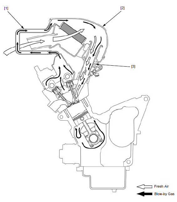
CRANKCASE EMISSION CONTROL SYSTEM
The engine is equipped with a closed crankcase system to prevent discharging crankcase emissions into the atmosphere. Blow-by gas is returned to the combustion chamber through the crankcase breather hose [1] air cleaner housing [2] and throttle body [3].
EXHAUST EMISSION CONTROL SYSTEM
The exhaust emission control system is composed of a pulse secondary air supply system, 3-way catalytic converter and PGM-FI system.
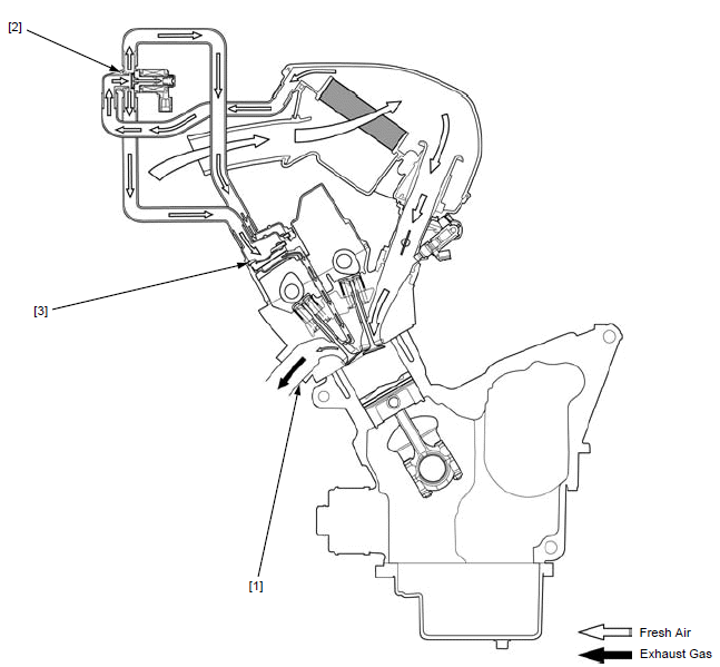
SECONDARY AIR SUPPLY SYSTEM
The pulse secondary air supply system introduces filtered air into the exhaust gases in the exhaust port [1]. Fresh air is drawn into the exhaust port by the function of the PAIR control solenoid valve [2].
This charge of fresh air promotes burning of the unburned exhaust gases and changes a considerable amount of hydrocarbons and carbon monoxide into relatively harmless carbon dioxide and water vapor.
The PAIR check valve [3] prevents reverse air flow through the system. The PAIR control solenoid valve is controlled by the PGM-FI unit, and the fresh air passage is opened/closed according to running condition (ECT/IAT/TP/MAP sensor and engine revolution).
No adjustments to the secondary air supply system should be made, although periodic inspection of the components is recommended.
3-WAY CATALYTIC CONVERTER
This motorcycle is equipped with a 3-way catalytic converter. The 3-way catalytic converter is in the exhaust system. Through chemical reactions, they convert HC, CO and NOX in the engine's exhaust to carbon dioxide (CO2), dinitrogen (N2), and water vapor.
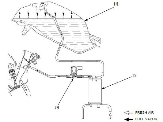
EVAPORATIVE EMISSION CONTROL SYSTEM (TH MODEL ONLY)
Fuel vapor from the fuel tank [1] is routed into the evaporative emission (EVAP) canister [2] where is it absorbed and stored while the engine is stopped. When the engine is running and the evaporative emission (EVAP) purge control solenoid valve [3] is open, fuel vapor in the EVAP canister is drawn into the engine through the intake pipe.
NOISE EMISSION CONTROL SYSTEM
TAMPERING WITH THE NOISE CONTROL SYSTEM IS PROHIBITED: Local law may prohibit the following acts or the causing there of: (1) The removal or rendering inoperative by any person, other than for purposes of maintenance, repair or replacement, of any device or element of design incorporated into any vehicle for the purpose of noise control prior to its sale or delivery to the ultimate customer or while it is in use; (2) the use of the vehicle after such device or element of design has been removed or rendered inoperative by any person.
AMONG THOSE ACTS PRESUMED TO CONSTITUTE TAMPERING ARE THE ACTS LISTED BELOW:
1. Removal of, or puncturing of the muffler, baffles, header pipes or any other component which conducts exhaust gases.
2. Removal of, or puncturing of any part of the intake system.
3. Lack of proper maintenance.
4. Replacing any moving parts of the vehicle, or parts of the exhaust or intake system, with parts other than those specified by the manufacturer.
Technical feature
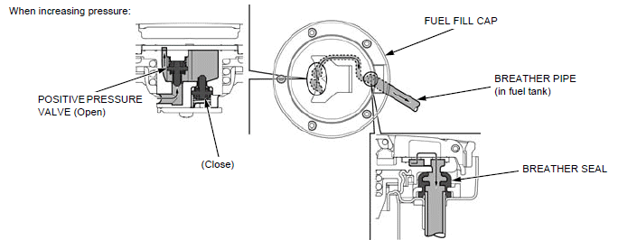
FUEL FILL CAP BREATHER
The fuel tank breather function of this model is controlled by the two one-way valves (positive and negative pressure valves) in the fuel fill cap as a substitute for a conventional vapor-liquid separator in the fuel tank.
COMPONENT FUNCTION
VALVES
Regulate the internal pressure of the fuel tank (they are closed with the spring until each specified pressure). In addition, spilling fuel to the outside is reduced when a fall-down has occurred.
BREATHER SEAL
The connecting section of the fuel fill cap and tank of the breather passage is prevented from leaking.
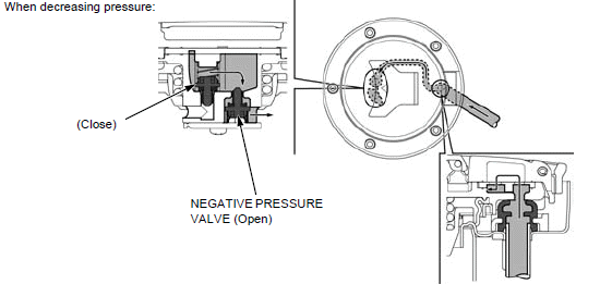
VALVE OPERATION
POSITIVE PRESSURE VALVE: When the tank internal pressure increases by fuel vapor, the positive pressure valve opens to release excess pressure out of the tank.
NEGATIVE PRESSURE VALVE: When the tank internal pressure decreases (fuel consumption etc.), the negative pressure valve opens and introduces air (TH model) including stored fuel vapor in the EVAP canister) into the tank.
- When opening the fuel fill cap, it will be sounded for pressure releasing, but it is not blockage of the passage. If checking for clogs in the fuel tank side passage is necessary, apply air pressure to the breather hose end while opening the fuel fill cap.
- Always replace the breather seal with a new one when the fuel fill cap is removed for service.
- Check the breather seal for deterioration, cracks or damage in accordance with the maintenance schedule "Evaporative Emission Control System (TH model)".
See also:
 Honda CBR650 - Service manual > Service rules
1. Use genuine Honda or Honda-recommended parts and lubricants or their equivalents. Parts that do not meet Honda's design specifications may cause damage to the motorcycle. 2. Use the special tools designed for this product to avoid damage and incorrect assembly.
Honda CBR650 - Service manual > Frame/body panels/exhaust system
SERVICE INFORMATION GENERAL This section covers removal and installation of the body panels and exhaust system. When disassembling, mark and store the mounting fasteners to ensure that they are reinstalled in their original locations. When installing the covers, make sure the mating areas are aligned properly before tightening the fasteners. Always replace the gaskets with new ones after removing the exhaust system. When installing the exhaust system, loosely install all of the fasteners. Always tighten the exhaust pipe joint nuts first, then tighten the mounting bolt. Always inspect the exhaust system for leaks after installation.
 Rider's Manual BMW R 1250 GS GSA
 Owner's Manual Harley-Davidson Sportster XL1200X Forty-Eight
 Owner's Manual Honda CBR650R
 Service manual Honda CBR650
 Owner's Manual Honda PCX125
 Owner's Manual Kawasaki Z1000SX
 Service manual Kawasaki Z1000SX
 Owner's Manual Lexmoto Echo
 Owner's Manual Royal Enfield Interceptor 650
 Service manual Royal Enfield Interceptor 650
 Owner's Manual Yamaha MT-07