 Kawasaki Z1000SX - Service manual > Exhaust Butterfly Valve Actuator Sensor (Service Code 34)
Exhaust Butterfly Valve Actuator Sensor Removal/Installation
The exhaust butterfly valve actuator sensor is built in the exhaust butterfly valve actuator. So, the sensor itself can not be removed. Remove the exhaust butterfly valve actuator (see Exhaust Butterfly Valve Actuator Removal).
Exhaust Butterfly Valve Actuator Sensor Input Voltage Inspection
NOTE
- Be sure the battery is fully charged.
- Turn the ignition switch OFF.
- Remove the front seat (see Front Seat Removal in the Frame chapter).
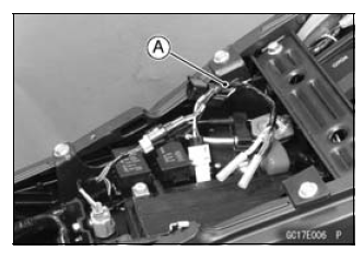
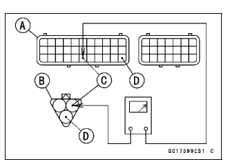
- Disconnect the exhaust butterfly valve actuator sensor lead connector (3 pins connector) and connect the harness adapter [A] between these connector.
Special Tool - Throttle Sensor Setting Adapter #1: 57001 -1400
- Connect a digital meter to the harness adapter leads.
Exhaust Butterfly Valve Actuator Sensor Input Voltage
Connections to Adapter:
Digital Meter (+) → Y/W (actuator W) lead
Digital Meter (−) → BK/BL (actuator BK) lead
- Measure the input voltage with the engine stopped and with the connector joined.
- Turn the ignition switch ON.
Input Voltage
Standard: DC 4.75 - 5.25 V
- Turn the ignition switch OFF.
If the reading is within the standard, check the output voltage (see Exhaust Butterfly Valve Actuator Sensor Output Voltage Inspection).
If the reading is out of the standard, remove the ECU and check the wiring for continuity between main harness connectors.
- Disconnect the ECU and sensor connectors.
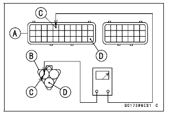
Wiring Inspection
ECU Connector [A] ←→
Exhaust Butterfly Valve Actuator Sensor Connector [B]
BL lead (ECU terminal 5) [C]
BR/BK lead (ECU terminal 33) [D]
If the wiring is good, check the ECU for its ground and power supply (see ECU Power Supply Inspection).
If the ground and power supply are good, replace the ECU (see ECU Removal/Installation).
Exhaust Butterfly Valve Actuator Sensor Output Voltage Inspection
NOTE
- Before this inspection, confirm the pulley [A] is original position (see Exhaust Butterfly Valve Actuator Installation).
- Disconnect:
2 pins Connector [B]
3 pins Connector [C]
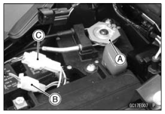
- Connect the harness adapter [A] between the 3 pins connectors.
Special Tool - Throttle Sensor Setting Adapter #1: 57001 -1400
- Connect a digital meter to the harness adapter leads.
Exhaust Butterfly Valve Actuator Sensor Output Voltage
Connections to Adapter:
Digital Meter (+) → BL (actuator Y) lead
Digital Meter (−) → BK/BL (actuator BK) lead
- Measure the output voltage at the 3 pins connector of the exhaust butterfly valve actuator when the pulley is original position.
- Turn the ignition switch ON.
Output Voltage
Standard: DC 3.46 - 3.76 V at pulley original position
- Turn the ignition switch OFF.
If the reading is out of the standard, check the exhaust butterfly valve actuator sensor resistance (see Exhaust Butterfly Valve Actuator Sensor Resistance Inspection).
If the reading is within the standard, remove the ECU and check the wiring for continuity between main harness connectors.
- Disconnect the ECU and sensor connectors.
Wiring Inspection
ECU Connector [A] ←→
Exhaust Butterfly Valve Actuator Sensor Connector [B]
R/BK lead (ECU terminal 28) [C]
BR/BK lead (ECU terminal 33) [D]
If the wiring is good, check the ECU for its ground and power supply (see ECU Power Supply Inspection).
If the ground and power supply are good, replace the ECU (see ECU Removal/Installation).
Exhaust Butterfly Valve Actuator Sensor Resistance Inspection
- Turn the ignition switch OFF.
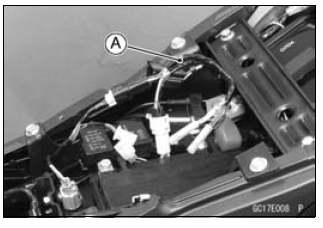
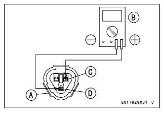
- Disconnect the exhaust butterfly valve actuator sensor connector (3 pins connector) [A].
- Connect a digital meter [B] to the exhaust butterfly valve actuator sensor connector.
- Measure the exhaust butterfly valve actuator sensor resistance.
Exhaust Butterfly Valve Actuator Sensor Resistance
Connections: W lead [C] ←→ BK lead [D]
Standard: 4 - 6 kΩ
If the reading is out of the standard, replace the exhaust butterfly valve actuator.
If the reading within the standard, but the problem still exists, replace the ECU (see ECU Removal/Installation).
Exhaust Butterfly Valve Actuator Sensor Circuit
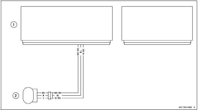
- ECU
- Exhaust Butterfly Valve Actuator
See also:
 Kawasaki Z1000SX - Service manual > Oxygen Sensor - not activated (Service Code 33, Equipped Models)
Oxygen Sensor Removal/Installation Refer to the Oxygen Sensor Removal/Installation in the Electrical System chapter. Oxygen Sensor Inspection Warm up the engine thoroughly until the radiator fan starts. Turn the ignition switch OFF. Remove the right fairing (see Lower Fairing Removal in the Frame chapter). Open the clamp [A], and pull out the oxygen sensor lead connector [B]. Disconnect the oxygen sensor lead connector (4 pins connector) and connect the harness adapter [A] between these connectors.
Kawasaki Z1000SX - Service manual > Immobilizer Amplifier (Service Code 35, Equipped Models)
Antenna Resistance Inspection Turn the ignition switch OFF. Remove the left lower fairing (see Lower Fairing Removal in the Frame chapter). Remove the band [A]. Disconnect the antenna lead connector [A]. Measure the antenna resistance.
 Rider's Manual BMW R 1250 GS GSA
 Owner's Manual Harley-Davidson Sportster XL1200X Forty-Eight
 Owner's Manual Honda CBR650R
 Service manual Honda CBR650
 Owner's Manual Honda PCX125
 Owner's Manual Kawasaki Z1000SX
 Service manual Kawasaki Z1000SX
 Owner's Manual Lexmoto Echo
 Owner's Manual Royal Enfield Interceptor 650
 Service manual Royal Enfield Interceptor 650
 Owner's Manual Yamaha MT-07