 Kawasaki Z1000SX - Service manual > Exhaust Butterfly Valve Actuator (Service Code 63)
Exhaust Butterfly Valve Actuator Removal
NOTICE Never drop the exhaust butterfly valve actuator especially on a hard surface. Such a shock to the actuator can damage it.
- Remove:
Front Seat (see Front Seat Removal in the Frame chapter)
Exhaust Butterfly Valve Cables (see Exhaust Butterfly Valve Cable Removal in the Engine Top End chapter)
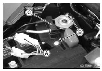
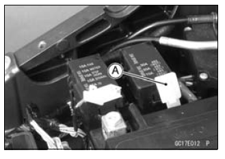
Connectors [A]
Screws [B]
Exhaust Butterfly Valve Actuator [C]
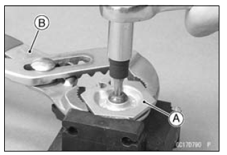
- Remove the pulley bolt while holding the pulley [A] with the suitable tool [B].
NOTICE If the pulley bolt is removed without holding, the actuator damage will occur.
- Remove the pulley from the actuator.
Exhaust Butterfly Valve Actuator Installation
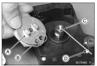
- Install the pulley [A] on the actuator so that the hole side [B] align
with the groove [C] on the shaft.
- Make sure that the groove on the shaft is pointing toward the center of the screw [D].
- If the shaft position is incorrect, refer to the following NOTE and procedures to electrically adjust the shaft position.
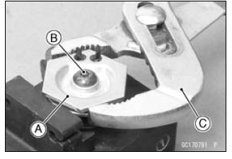
- Install the pulley [A] on the actuator as shown.
- Tighten the pulley bolt [B] while holding the pulley with the suitable tool [C].
Torque - Exhaust Butterfly Valve Actuator Pulley Bolt: 5.0 N*m (0.51 kgf*m, 44 in*lb)
NOTICE If the pulley bolt is tightened without holding, the actuator damage will occur.
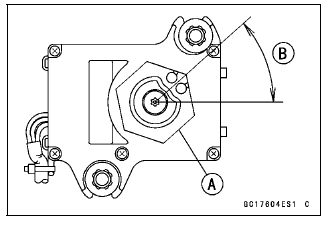
- After tightening the pulley bolt, confirm whether pulley [A] is an angle
shown in the figure.
41.7º +-7º [B]
- This position is original position of the pulley.
NOTE
- Correct the position electrically after confirming the use is discontinued and there is no damage when differing from the angle of shown in the figure.
NOTICE Do not correct the pulley position with the tool, forcibly. The actuator damage will occur.
If the pulley angle is wrong, adjust the angle as follows.
- Connect:
2 pins Connector
3 pins Connector- Turn the ignition switch ON.
- Confirm the pulley turns clockwise or counterclockwise then it stops at the original position.
If the pulley position has not been returned to the original position, electrically adjust the shaft position as follows.
- Remove:
2 pins Connector
3 pins Connector- Turn the pulley to the original position by turning it clockwise or counterclockwise by connecting the battery to the 2 pins connector terminals. To turn the pulley gradually, intermittently connect the battery positive (+) terminal to the 2 pins connector terminal while connecting the battery negative (-) terminal to the connector.
Pink (-) lead terminal [A]
Gray (+) lead terminal [B]
Clockwise:
Pink (-) lead terminal to battery (-) terminal
Gray (+) lead terminal to battery (+) terminal
Counterclockwise:
Pink (-) lead terminal to battery (+) terminal
Gray (+) lead terminal to battery (-) terminal
- Reconnect the 2 pins connector and 3 pins connector, and turn the ignition switch ON.
- Make sure that the pulley turns clockwise and then counterclockwise.
- The pulley should returns to the original position.
- Turn the ignition switch OFF.
If the pulley does not return to the original position, check the exhaust butterfly valve actuator resistance (see Exhaust Butterfly Valve Actuator Resistance Inspection).
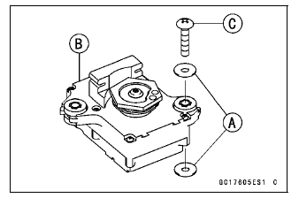
- Be sure to install the washers [A] on the exhaust butterfly valve actuator [B].
- Tighten:
Torque - Exhaust Butterfly Valve Actuator Mounting Screws [C]: 1.2 N *m (0.12 kgf *m, 11 in*lb) - Install the close cable first and then open cable (see Exhaust Butterfly Valve Cable Installation in the Engine Top End chapter).
Exhaust Butterfly Valve Actuator Inspection
NOTE
- Be sure the battery is fully charged
- Remove the front seat (see Front Seat Removal in the Frame chapter).
- Turn the ignition switch ON.
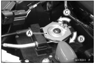
- In the left side view of the motorcycle, check to see the pulley [A]
clockwise [B] and counterclockwise [C] smoothly.
- The pulley turns clockwise and then counterclockwise, and clockwise again.
- Turn the ignition switch OFF.
If the pulley does not operate, check the exhaust butterfly valve cable installation (see Butterfly Valve Cable Installation in the Engine Top End chapter) and the exhaust butterfly valve actuator resistance (see Exhaust Butterfly Valve Actuator Resistance Inspection).
Exhaust Butterfly Valve Actuator Resistance Inspection
- Turn the ignition switch OFF.
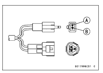
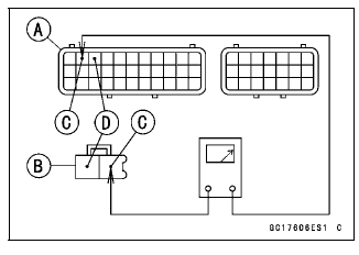
- Disconnect the exhaust butterfly valve actuator lead connector (2 pins connector) [A].
- Set the hand tester to the × 1 Ω range and connect it to the exhaust butterfly valve actuator connector.
Special Tool - Hand Tester: 57001-1394
- Measure the exhaust butterfly valve actuator resistance.
Exhaust Butterfly Valve Actuator Resistance
Connections: P lead ←→ GY lead
Standard: Any Reading Resistance (reference 5 - 200 Ω)
If the reading is 0 or infinity (∞) Ω, replace the exhaust butterfly valve actuator.
If the reading is in specification, remove the ECU and check the wiring for continuity between main harness connectors.
- Disconnect the ECU and actuator connectors.
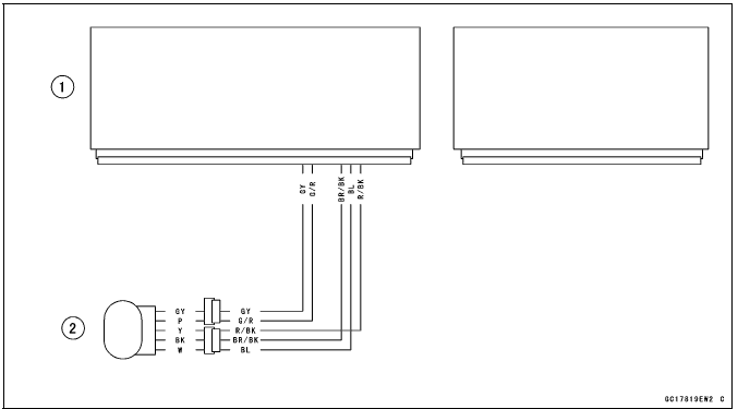
Wiring Inspection
ECU Connector [A] ←→
Exhaust Butterfly Valve Actuator Connector [B]
GY lead (ECU terminal 2) [C]
G/R lead (ECU terminal 3) [D]
If the wiring is good, check the ECU for its ground and power supply (see ECU Power Supply Inspection).
If the ground and power supply are good, replace the ECU (see ECU Removal/Installation).
Exhaust Butterfly Valve Actuator Circuit
- ECU
- Exhaust Butterfly Valve Actuator
Air Switching Valve (Service Code 64)
Air Switching Valve Removal/Installation
- Refer to the Air Switching Valve Removal/Installation in the Engine Top End chapter.
Air Switching Valve Inspection
- Refer to the Air Switching Valve Unit Test in the Electrical System
chapter.
If the air switching valve is normal, check the wiring for continuity (see wiring diagram in this section).
If the wiring is good, check the ECU for its ground and power supply (see ECU Power Supply Inspection).
If the ground and power supply are good, replace the ECU (see ECU Removal/Installation).
Air Switching Valve Circuit
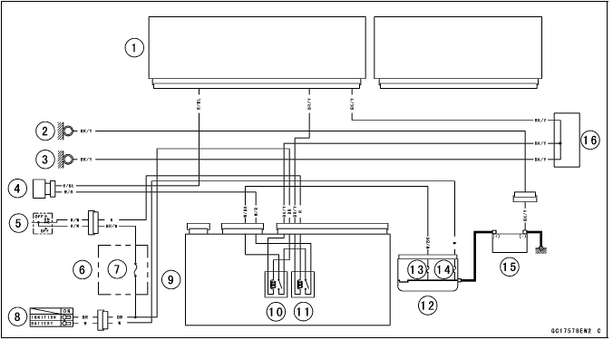
- ECU
- Meter Ground
- Frame Ground
- Air Switching Valve
- Engine Stop Switch
- Fuse Box 2
- Ignition Fuse 15 A
- Ignition Switch
- Relay Box
- ECU Main Relay
- Fuel Pump Relay
- Starter Relay
- FI Fuse 15 A
- Main Fuse 30 A
- Battery 12 V 8 Ah
- Water-proof Joint C
See also:
 Kawasaki Z1000SX - Service manual > Subthrottle Valve Actuator (Service Code 62)
Subthrottle Valve Actuator Removal NOTICE Do not remove the subthrottle valve actuator [A] since it has been adjusted and set with precision at the factory.
Kawasaki Z1000SX - Service manual > Oxygen Sensor Heater (Service Code 67, Equipped Models)
Oxygen Sensor Heater Removal/Installation The oxygen sensor heater is built in the oxygen sensor. So, the heater itself can not be removed. Remove the oxygen sensor (see Oxygen Sensor Removal (Equipped Models) in the Electrical System chapter).
 Rider's Manual BMW R 1250 GS GSA
 Owner's Manual Harley-Davidson Sportster XL1200X Forty-Eight
 Owner's Manual Honda CBR650R
 Service manual Honda CBR650
 Owner's Manual Honda PCX125
 Owner's Manual Kawasaki Z1000SX
 Service manual Kawasaki Z1000SX
 Owner's Manual Lexmoto Echo
 Owner's Manual Royal Enfield Interceptor 650
 Service manual Royal Enfield Interceptor 650
 Owner's Manual Yamaha MT-07