 Kawasaki Z1000SX - Service manual > Intake Air Pressure Sensor #1 (Service Code 12)
Intake Air Pressure Sensor #1 Removal
NOTICE Never drop the intake air pressure sensor #1 especially on a hard surface. Such a shock to the sensor can damage it.
- Remove:
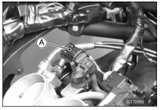
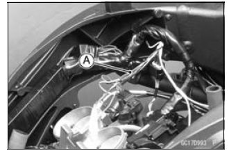
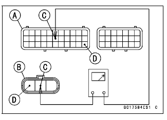
Air Cleaner Housing (see Air Cleaner Housing Removal) Intake Air Pressure Sensor #1 Connector [A]
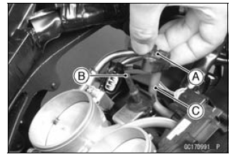
- Remove the intake air pressure sensor #1 [A] from the rubber damper [B] in the bracket and separate the vacuum hose [C].
Intake Air Pressure Sensor #1 Installation
NOTE
- The intake air pressure sensor #1 is the same part as the intake air pressure sensor #2.
- Installation is the reverse of removal.
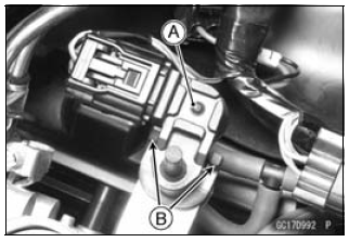
- Position the intake air pressure sensor #1 [A] between the projections [B] on the rubber damper.
Intake Air Pressure Sensor #1 Input Voltage Inspection
NOTE
- Be sure the battery is fully charged.
- Turn the ignition switch OFF.
- Remove the air cleaner housing (see Air Cleaner Housing Removal).
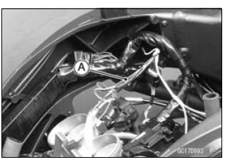
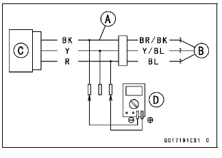
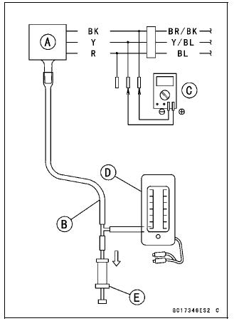
- Disconnect the intake air pressure sensor #1 connector and connect the
harness adapter [A] between these connectors.
[B] Main Harness
[C] Intake Air Pressure Sensor #1
Special Tool - Measuring Adapter: 57001-1700
- Connect a digital meter [D] to the harness adapter leads.
Intake Air Pressure Sensor #1 Input Voltage
Connections to Adapter:
Digital Meter (+) → R (sensor BL) lead
Digital Meter (-) → BK (sensor BR/BK) lead
- Measure the intake voltage with the engine stopped and with the connector joined.
- Turn the ignition switch ON.
Input Voltage Standard: DC 4.75 - 5.25 V
- Turn the ignition switch OFF.
If the reading is within the standard, check the output voltage (see Intake Air Pressure Sensor #1 Output Voltage Inspection).
If the reading is out of the standard, remove the ECU and check the wiring for continuity between main harness connectors.
Special Tool - Hand Tester: 57001-1394
- Disconnect the ECU and sensor connectors.
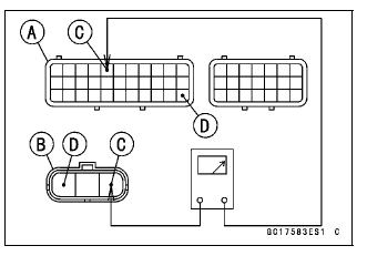
Wiring Continuity Inspection
ECU Connector [A] ←→
Intake Air Pressure Sensor #1 Connector [B]
BL lead (ECU terminal 5) [C]
BR/BK lead (ECU terminal 33) [D]
If the wiring is good, check the ECU for its ground and power supply (see ECU Power Supply Inspection).
If the ground and power supply are good, replace the ECU (see ECU Removal/Installation).
Intake Air Pressure Sensor #1 Output Voltage Inspection
- Measure the output voltage at the intake air pressure sensor #1 in the same way as input voltage inspection, note the following.
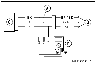
- Disconnect the intake air pressure sensor #1 connector and connect the
harness adapter [A] between these connectors.
[B] Main Harness
[C] Intake Air Pressure Sensor #1
[D] Digital Meter
Special Tool - Measuring Adapter: 57001-1700
Intake Air Pressure Sensor #1 Output Voltage
Connections to Adapter:
Digital Meter (+) → Y (sensor Y/BL) lead
Digital Meter (-) → BK (sensor BR/BK) lead
- Measure the output voltage with the engine stopped and with the connector joined.
- Turn the ignition switch ON.
Output Voltage
Usable Range: DC 3.80 - 4.20 V at standard atmospheric pressure (101.32 kPa, 76
cmHg)
NOTE
- The output voltage changes according to local atmospheric pressure.
- Turn the ignition switch OFF.
If the reading is out of the usable range, replace the sensor.
If the reading is within the usable range, remove the ECU and check the wiring for continuity between main harness connector.
Special Tool - Hand Tester: 57001-1394
- Disconnect the ECU and sensor connectors.
Wiring Continuity Inspection
ECU Connector [A] ←→
Intake Air Pressure Sensor #1 Connector [B]
Y/BL lead (ECU terminal 17) [C]
BR/BK lead (ECU terminal 33) [D]
If the wiring is good, check the sensor for various vacuum.
- Remove the intake air pressure sensor #1 [A] and disconnect the vacuum hose from the sensor.
- Connect an auxiliary hose [B] to the intake air pressure sensor #1.
- Temporarily install the intake air pressure sensor #1.
- Connect a digital meter [C], vacuum gauge [D], the fork oil level gauge [E] and the harness adapter to the intake air pressure sensor #1.
Special Tools -
Fork Oil Level Gauge: 57001-1290
Vacuum Gauge: 57001-1369
Measuring Adapter: 57001-1700
Intake Air Pressure Sensor #1 Output Voltage
Connections to Adapter:
Digital Meter (+) → Y (sensor Y/BL) lead
Digital Meter (-) → BK (sensor BR/BK) lead
- Turn the ignition switch ON.
- Measure the intake air pressure sensor #1 output voltage from various vacuum readings, while pulling the handle of the fork oil level gauge.
- Check the intake air pressure sensor #1 output voltage, using the following formula and chart.
Suppose:
Pg: Vacuum Pressure (Gauge) of Throttle Body
Pl: Local Atmospheric Pressure (Absolute) measured by a barometer
Pv: Vacuum Pressure (Absolute) of Throttle Body
Vv: Sensor Output Voltage (V)
then
Pv = Pl - Pg
For example, suppose the following data is obtained:
Pg = 8 cmHg (Vacuum Gauge Reading)
Pl = 70 cmHg (Barometer Reading)
Vv = 3.2 V (Digital Meter Reading)
then
Pv = 70 - 8 = 62 cmHg (Absolute)
Plot this Pv (62 cmHg) at a point [1] on the chart and draw a vertical line through the point. Then, you can get the usable range [2] of the sensor output voltage.
Usable range = 3.08 - 3.48 V
Plot Vv (3.2 V) on the vertical line. → Point [3].
Results: In the chart, Vv is within the usable range and the sensor is normal.
If the reading is out of the usable range, replace the sensor.
If the reading is within the usable range, check the ECU for its ground and power supply (see ECU Power Supply Inspection).
If the ground and power supply are good, replace the ECU (see ECU Removal/Installation).
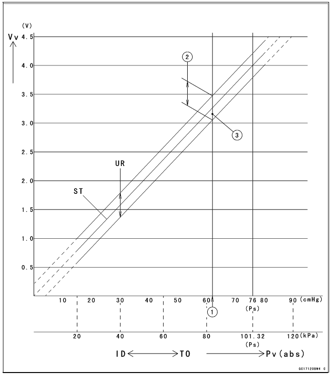
ID: Idling
Ps: Standard Atmospheric Pressure (Absolute)
Pv: Throttle Vacuum Pressure (Absolute)
ST: Standard of Sensor Output Voltage (V)
TO: Throttle Full Open
UR: Usable Range of Sensor Output Voltage (V)
Vv: Intake Air Pressure Sensor #1 Output Voltage (V) (Digital Meter Reading)
Intake Air Pressure Sensor #1 Circuit
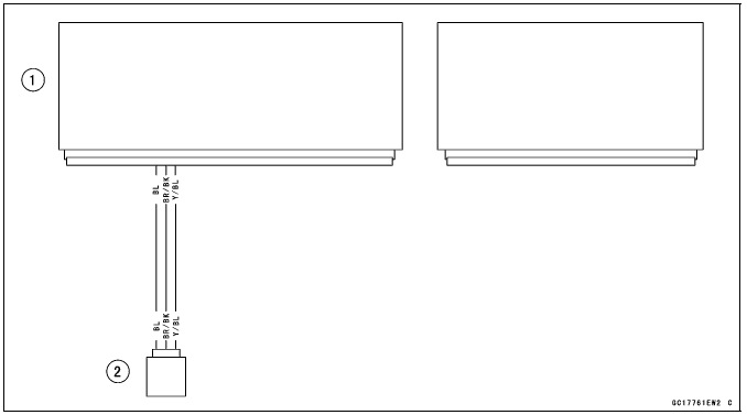
- ECU
- Intake Air Pressure Sensor #1
See also:
 Kawasaki Z1000SX - Service manual > Main Throttle Sensor (Service Code 11)
The main throttle sensor is a rotating variable resistor that change output voltage according to throttle operating. The ECU senses this voltage change and determines fuel injection quantity, and ignition timing according to engine rpm, and throttle opening.
Kawasaki Z1000SX - Service manual > Intake Air Temperature Sensor (Service Code 13)
Intake Air Temperature Sensor Removal/Installation NOTICE Never drop the intake air temperature sensor especially on a hard surface. Such a shock to the sensor can damage it. Remove the fuel tank (see Fuel Tank Removal). Disconnect the connector [A] from the intake air temperature sensor [B]. Remove: Screw [C] Intake Air Temperature Sensor Be sure to install the O-ring [A]. Install the intake air temperature sensor. Tighten: Torque - Intake Air Temperature Sensor Mounting Screw: 1.2 N*m (0.12 kgf*m, 11 in*lb)
 Rider's Manual BMW R 1250 GS GSA
 Owner's Manual Harley-Davidson Sportster XL1200X Forty-Eight
 Owner's Manual Honda CBR650R
 Service manual Honda CBR650
 Owner's Manual Honda PCX125
 Owner's Manual Kawasaki Z1000SX
 Service manual Kawasaki Z1000SX
 Owner's Manual Lexmoto Echo
 Owner's Manual Royal Enfield Interceptor 650
 Service manual Royal Enfield Interceptor 650
 Owner's Manual Yamaha MT-07