 Kawasaki Z1000SX - Service manual > Wheel Rotation Sensor Signal Abnormal [Too High Speed] (Service
Code 93)
Kawasaki Z1000SX - Service manual > Wheel Rotation Sensor Signal Abnormal [Too High Speed] (Service
Code 93)
- When the wheel rotation sensor signal detects 340 km/h or more at a motor cycle speed of 264 km/h or more, this service code is detected. Therefore, this service code might be detected by a special operation condition or using the substandard tire.
- Recheck the service code indication; erase the service code, perform the
pre-diagnosis inspection 1 and 2, and retrieve the service code.
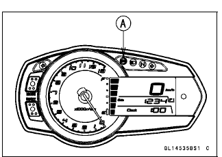
If the ABS indicator light (LED) [A] lights, the ABS hydraulic unit has trouble. Replace the ABS hydraulic unit.
If the ABS indicator light (LED) does not light, ABS system is normal (service code is not stored; temporary failure.).
ABS Hydraulic Unit Removal
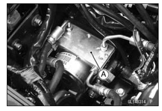
NOTICE The ABS hydraulic unit [A] has been adjusted and set with precision at the factory. Therefore, it should be handled carefully, never struck sharply, as with a hammer, or allowed to fall on a hard surface.
Be careful not to get water or mud on the ABS hydraulic unit.
- Drain the brake fluid from the front and rear brake lines.
- Drain the brake fluid through the bleed valve by pumping the brake lever and pedal.
- Remove:
Battery Case (see Battery Case Removal in the Frame chapter)
Brake Hose (see Brake Hose Replacement in the Periodic maintenance chapter) - Clean the ABS hydraulic unit.
NOTICE Clean all fittings on the ABS hydraulic unit and the rear master cylinder because dirt around the banjo bolts could contaminate the brake fluid in the line during removal/installation.
Spread over a shop towel around the ABS hydraulic unit before removing the brake line so that brake fluid does not leak on the parts.
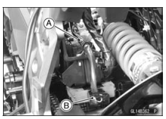
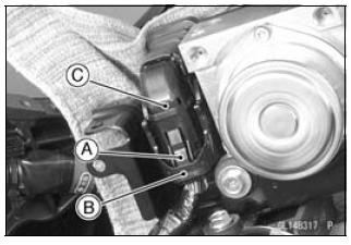
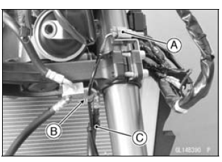
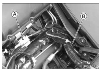
- Open the clamp [A].
- Disconnect the regulator/rectifier connector [B].
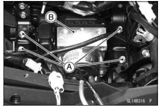
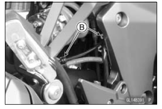
- Remove the bolts [A].
- Pull up the ABS hydraulic unit [B].
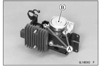
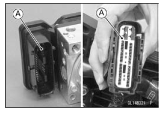
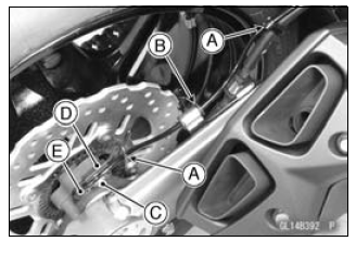
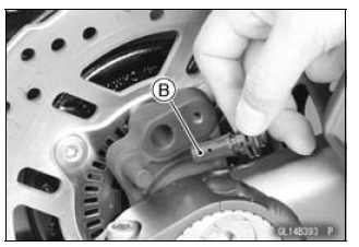
- While pushing the stopper [A], unlock the connector lock [B] upward.
- Disconnect the connector [C].
- Remove:
Bolts [A]
ABS Hydraulic Unit [B]
NOTICE The ABS hydraulic unit [A] has been adjusted and set with precision at the factory. Do not try to disassemble and repair the ABS hydraulic unit.
ABS Hydraulic Unit Installation
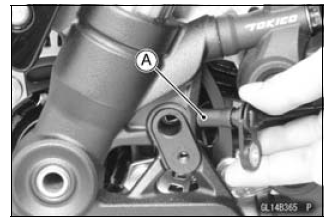
- Install the ABS hydraulic unit to the bracket.
NOTICE Brake fluid quickly ruins painted plastic surfaces; any spilled fluid should be completely washed away immediately.
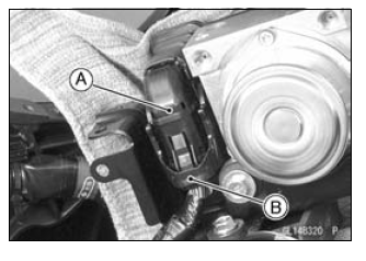
- Run the lead correctly, and connect the connector [A] securely.
- Lock the connector lock [B] as shown in the figure.
- Install the brake hoses correctly (see Brake Hose Replacement in the Periodic Maintenance chapter).
- Bleed the brake line (see Brake Line Bleeding).
- Check the brake for good braking power, no brake drag, and no fluid leakage.
- Install the removed parts (see appropriate chapters).
ABS Hydraulic Unit Inspection
- Remove the ABS hydraulic unit (see ABS Hydraulic Unit Removal).
- Visually inspect the ABS hydraulic unit.
Replace the ABS hydraulic unit if any of them are cracked, or otherwise damaged.
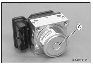
- Visually inspect the connector terminals [A].
Replace the ABS hydraulic unit or main harness if either of the terminals are cracked, bent, or otherwise damaged.
If the ABS hydraulic unit connector is clogged with mud or dust, blow it off with compressed air.
Front Wheel Rotation Sensor Removal
NOTICE The wheel rotation sensor should be handled carefully, never struck sharply, as with a hammer, or allowed to fall on a hard surface since the wheel rotation sensor is precision made. Be careful not to get water or mud on the wheel rotation sensor.
Do not try to disassemble or repair the wheel rotation sensor.
- Remove:
Upper Fairing (see Upper Fairing Removal in the Frame chapter)
Connector [A] (Disconnect)
Grommet [B]
Clamp [C]
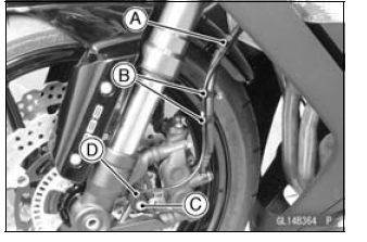
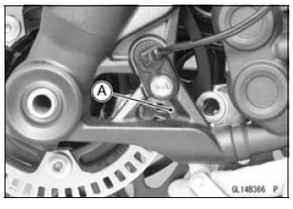
- Remove:
Clamp [A] - Clear the sensor lead from the clamps [B].
- Remove:
Bolt [C]
Front Wheel Rotation Sensor [D]
Front Wheel Rotation Sensor Installation
- Installation is the reverse of removal.
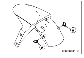
- Replace the brake hose clamp with a new one (ZX1000HB Early Model).
- For ZX1000HB Late Model -, face the lock portion [A] of the brake hose clamp backward.
- Run the lead correctly (see Cable, Wire, and Hose Routing section in the Appendix chapter).
Rear Wheel Rotation Sensor Removal
NOTICE The wheel rotation sensor should be handled carefully, never struck sharply, as with a hammer, or allowed to fall on a hard surface since the wheel rotation sensor is precision made. Be careful not to get water or mud on the wheel rotation sensor.
Do not try to disassemble or repair the wheel rotation sensor.
- Remove:
Fuel Tank (see Fuel Tank Removal in the Fuel System (DFI) chapter)
Connector [A] (Disconnect) - Clear the sensor lead from the clamps [B].
- Clear the sensor lead from the clamps [A].
- Remove:
Grommet [B]
Bolt [C]
Clamp [D]
Rear Wheel Rotation Sensor [E]
Rear Wheel Rotation Sensor Installation
- Installation is the reverse of removal.
- Run the lead correctly (see Cable, Wire, and Hose Routing section in the Appendix chapter).
Wheel Rotation Sensor Inspection
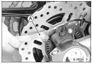
- Remove the front wheel rotation sensor [A] from the front fork.
- Remove the rear wheel rotation sensor [B] from the caliper bracket.
- Visually inspect the wheel rotation sensors.
Replace the wheel rotation sensor if it is cracked, bent, or otherwise damaged.
Wheel Rotation Sensor Air Gap Inspection
- Raise the front/rear wheel off the ground (see Front/Rear Wheel Removal in the Wheels/Tires chapter).
- Measure the air gap between the sensor and sensor rotor at several
points by turning the wheel slowly.
Thickness Gauge [A]
Air Gap
Standard:
Front 1.98 - 2.86 mm (0.0780 - 0.113 in.)
Rear 1.12 - 1.85 mm (0.0441 - 0.0728 in.)
NOTE
- The sensor air gap cannot be adjusted.
If the air gap is not within the specification, inspect the hub bearing (see Hub Bearing Inspection in the Wheels/Tires chapter), sensor installation condition and sensor (see Wheel Rotation Sensor Inspection).
Wheel Rotation Sensor Rotor Inspection
- Remove:
Wheels (see Front/Rear Wheel Removal in the Wheels/Tires chapter)
Brake Disc Mounting Bolts [A]
Sensor Rotor [B]
Front Wheel [C]
Rear Wheel [D]
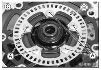
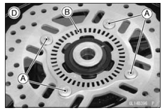
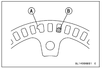
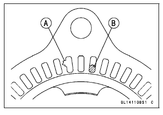
- Visually inspect the wheel rotation sensor rotor.
If the rotor is deformed or damaged (chipped teeth [A]), replace the sensor rotor with a new one.
If there is iron or other magnetic deposits [B], remove the deposits.
ABS Solenoid Valve Relay Fuse (20 A) Removal
- Refer to the Fuse Box Fuse Removal in the Electrical System chapter.
ABS Motor Relay Fuse (30 A) Removal
- Refer to the Fuse Box Fuse Removal in the Electrical System chapter.
ABS ECU Fuse (10 A) Removal
- Refer to the Fuse Box Fuse Removal in the Electrical System chapter.
Fuse Installation
- If a fuse fails during operation, inspect the electrical system to determine the cause, and then replace it with a new fuse of proper amperage (see Fuse Installation in the Electrical System chapter).
Fuse Inspection
- Remove the fuses (see ABS Solenoid Valve Relay Fuse (20 A)/ABS Motor Relay Fuse (30 A)/ABS ECU Fuse (10 A) Removal).
- Refer to the Fuse Inspection in the Electrical System chapter.
See also:
 Kawasaki Z1000SX - Service manual > Rear Wheel Rotation Sensor Signal Abnormal (Service Code 44)
Measure the air gap between the rear wheel rotation sensor and sensor rotor (see Wheel Rotation Sensor Air Gap Inspection). Check the rear wheel rotation sensor (see Rear Wheel Rotation Sensor Inspection).
 Rider's Manual BMW R 1250 GS GSA
 Owner's Manual Harley-Davidson Sportster XL1200X Forty-Eight
 Owner's Manual Honda CBR650R
 Service manual Honda CBR650
 Owner's Manual Honda PCX125
 Owner's Manual Kawasaki Z1000SX
 Service manual Kawasaki Z1000SX
 Owner's Manual Lexmoto Echo
 Owner's Manual Royal Enfield Interceptor 650
 Service manual Royal Enfield Interceptor 650
 Owner's Manual Yamaha MT-07