 Royal Enfield Interceptor 650 - Service manual > Anti-lock Braking System (ABS)
Working Principle
The Royal Enfield Continental GT 650 twin and Interceptor 650 twin motorcycles are equipped with the state of the art Anti-Lock Braking System (ABS).
The ABS is a safety system which constantly receives inputs about the speed of rotation of the front and rear wheels on a real time basis and modulates the braking force for each wheel when brakes are applied by the rider. This helps prevent the brakes from locking the wheels, especially when brakes are applied suddenly, the wheels have a better traction with the road surface. The benefits of ABS:
- Increased braking efficiency and riding confidence when braking.
- Prevent wheel lock up when brakes are applied suddenly with great force thereby ensuring good traction of the front and rear wheels with the road surface.
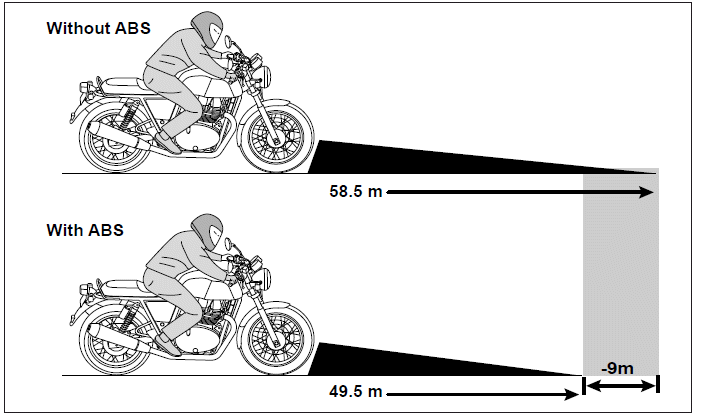
Typical Motorcycle Braking Distance
(Average driver starting speed 100 Kmph)
The ABS consists of an Electronic Control Unit (ECU), modulator, toner rings and wheel speed sensors. The ECU constantly receives inputs on the speed of rotation of the front and rear wheels through the wheel speed sensors. When the rider applies either the front or rear brakes or both brakes, the speed sensors provide data on the rate of deceleration of the wheels to the ECU which then commands the valves in the modulator to progres-sively regulate the hydraulic fluid pressure on a real time basis so that the brake pads do not "lock" on the brake disc which can potentially cause the wheels to lock.
Whenever front and/or rear brakes are applied with great force/suddenly, the braking management system gets input of the wheels speed through a wheel speed sensor and commands the modulator in the braking system to modulate the hydraulic fluid force such that the brake pads do not lock on the brake disc which effectively from locking and provide better traction to prevent the motor cycle from shifting and/or loss of control.
In the ABS, during application of brakes, a pulsating sensation will be felt on the brake lever/pedal indicating that the ABS is working correctly.
WARNING The ABS will by no means prevent an accident and/or loss of control. It is the responsibility of the rider to anticipate and judge the braking distances required, depending on the speed at which the motorcycle is traveling and apply brakes sufficiently in advance to prevent an accident and/or loss of control.
While ABS assists in improved motorcycle control during braking, decreased stopping distances on dry and good road conditions, it cannot be assumed that it will be effective in wet, rainy, snow covered, off road conditions, loose gravel surfaces or hilly roads etc, as the traction of the wheel itself will be very minimal in these conditions.
As far as possible, whenever applying sudden brakes in emergency in wet conditions, please ensure the motorcycle is upright in steady riding position and the handlebars are straight. Avoid hard braking when banking heavily at great speeds.
Whenever brakes are applied, a pulsating sensation will be felt on the brake lever/pedal. This is characteristic to the ABS and quite normal, as the modulator in the ABS constantly modulates the hydraulic pressure in the braking system in relation to the force applied on the brake lever/pedal and the speed of the motorcycle.
Whenever bleeding the hydraulic system, it is highly recommended to bleed both the front and rear brakes for proper functioning of the ABS. Do not restrict to bleeding any one brake system as it may render the ABS non-functional, in case the other brake has air bubbles in its system.
Functions and Specifications of the ABS Aggregates
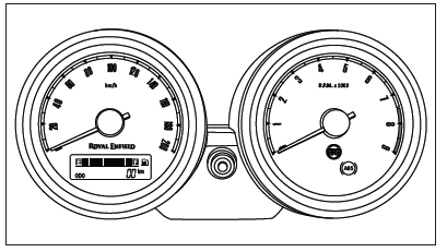
As soon as the ignition and engine stop switch are switched ON, the ABS sign will light up. The lamp will remain ON till the motorcycle attains a speed of 5 Kmph (3MPH) and then switches OFF. This indicates that the ABS is working properly.
In the event the lamp does not switch OFF and remains continuously ON at higher speeds, it is recommended not to drive the motorcycle and get the brake system inspected and corrected through a nearest authorized Royal Enfield Distributor.
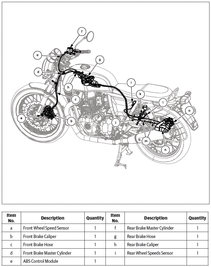
1. Electronic Control Unit (ECU)
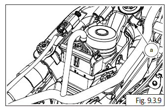
The ECU is located in the bracket alongside of the modulator, on the frame, below the fuel tank.
It consists of a microprocessor, which receives inputs from the wheel speed sensors, interprets the data, determines the safe hydraulic pressure in relation to the speed of the wheels and commands the valves in the modulator to progressively regulate the hydraulic fluid pressure on a real time basis for efficient and safe braking.
Specifications:
Operating Voltage: 09 V to 16 V
Operating Temperature: -40ºC to 70ºC
The ECU also records and stores data on the performance of the ABS on a real-time basis. This will help in diagnosing any braking related disorders, whenever the Royal Enfield NACS II diagnostic tool is connected to the socket in the wiring harness of the motorcycle.
The history stored in the ECU can also be saved to an external computer for future reference and also erased from the ECU, using the Royal Enfield NACS II diagnostic tool.
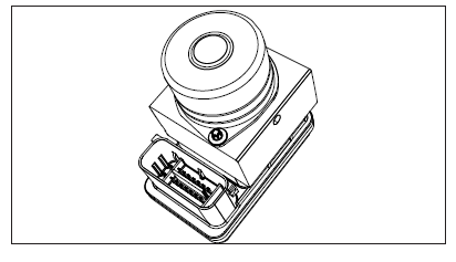
2. Modulator
The modulator is located on the frame below the fuel tank. The brake hoses from the master cylinders and brake calipers are connected to the modulator.
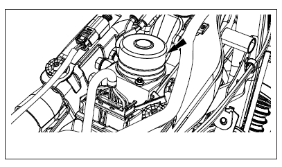
Whenever brakes are applied, the valves inside the modulator are progressively activated by the ECU to regulate the hydraulic fluid pressure in the brake system. This in turn will modulate the movement of the pistons inside the brake calipers to prevent the brake pads from locking on the brake discs.
3. Wheel Speed Sensors, Front and Rear
There are 2 wheel speed sensors provided in the motorcycle. The front speed sensor is assembled on the fork end LH and the rear speed sensor is assembled on the rear wheel caliper bracket.
Specifications:
Operating Voltage: 08 V to 16 V
Operating Temperature: -40º C to 70º C
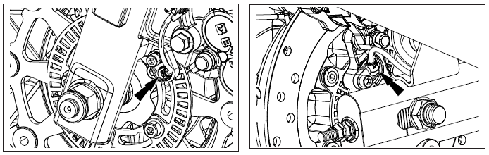
These sensors provide the inputs to the ECU about the speed of rotation of the wheels.
4. Toner Rings, Front and Rear
The toner rings are assembled on the front and rear brake hubs inside the brake discs.
The toner rings assists the wheel speed sensors to assess the speed of rotation of the wheels.
5. Master Cylinders, Front and Rear
The front brake master cylinder is assembled on the handlebar RH and activated by the front brake lever. The rear brake master cylinder is assembled on the frame RH side and activated by the brake pedal
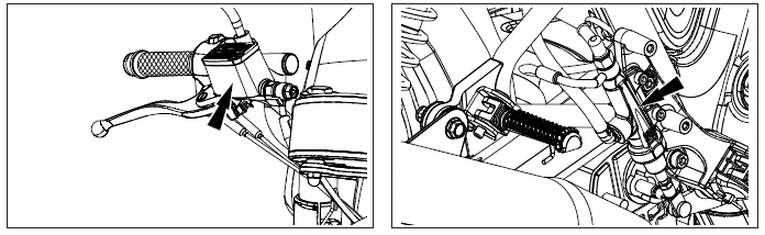
Whenever the front brake lever/rear brake pedal are activated, the piston inside the master cylinder applies force on the brake fluid to activate the brakes.
The master cylinders are connected to the modulator through brake hoses to transmit the applied hydraulic fluid pressure from the master cylinders.
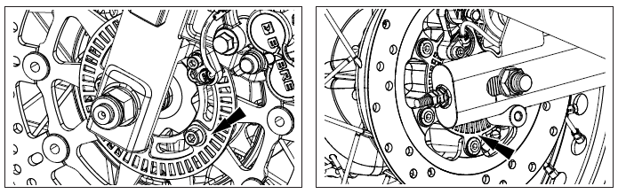
6. Wheel Calipers - Front and Rear
The front wheel caliper is assembled on the fork end LH and the rear wheel caliper is located on the rear swing arm RH. The wheel calipers consist of pistons and brake pads.
When brakes are applied, the hydraulic fluid force in the braking system causes the pistons to move, and pushes the brake pads against the brake discs on the wheels for braking.
The wheel calipers are connected to the modulator which modulate the hydraulic fluid force to be applied against the pistons.
Do's and Don'ts for ABS
- Use only approved Brake fluid recommended by Royal Enfield. ( DOT4 )
- Whenever the modulator is removed from the motorcycle, please ensure it is stored upright with the ports facing upwards.
- Whenever the modulator is removed from the motorcycle for any reason, please ensure the front and rear brake system bleeding is carefully done and no air is trapped in the brake system.
- DO NOT interchange ABS unit/ECU from one motorcycle to another.
- DO NOT interchange the brake hose connections between master cylinders and wheel cylinders and also front and rear circuit, at the modulator end.
- The shelf life of a wet modulator unit is 5 years from the date of manufacture.
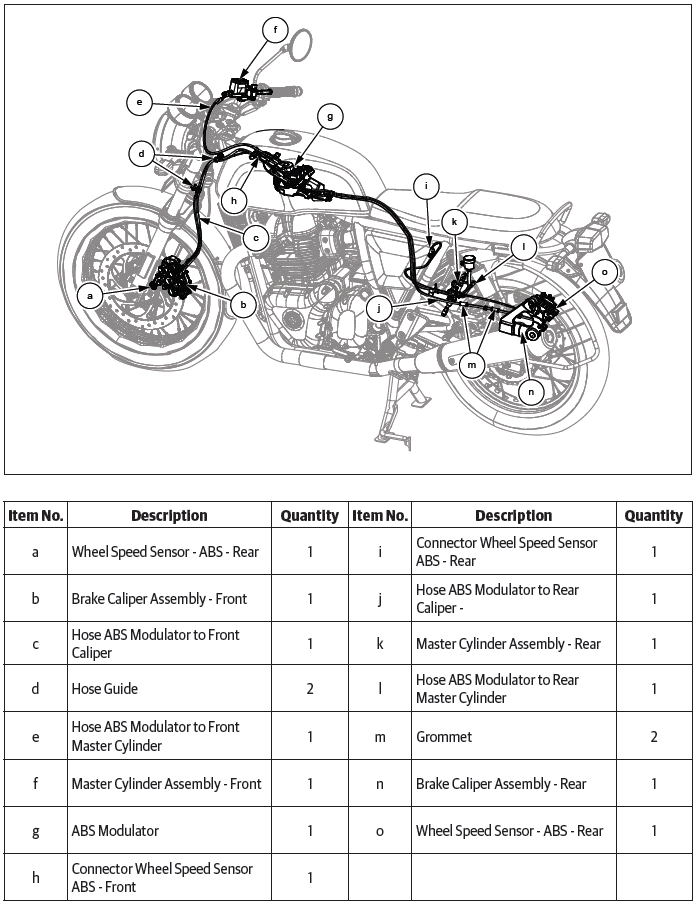
ABS Components
Dismantling
Modulator
CAUTION Before dismantling the modulator, ensure ignition switch and engine stop switch are in OFF position.
Ensure the hydraulic brake fluid from the front and rear brakes is drained completely.
- Remove the following parts:
- Side panel RH
- Rider seat
- Fuel tank assembly
CAUTION Ensure the following: Fuel is drained completely from fuel tank.
Fuel feed and return hoses are disconnected from the fuel rail.
Wiring couplers to fuel pump and low fuel sensors are disconnected.
EVAP hose pipes are disconnected.
WARNING Gasoline is extremely flammable and highly explosive. Improper handling can lead to fatal accident or serious injury.
- Bleed out the brake fluid from the front brake system.
CAUTION Do not spill brake fluid on any part of the motorcycle as it will damage the painted/ plastic surfaces.
WARNING Ensure brake fluid does not get in contact with eyes and skin. In-case of exposure wash affected area thoroughly with water. Seek medical attention immediately if any irritation persists.
Keep out of reach of children.
Dispose drained brake fluid carefully and responsibly.
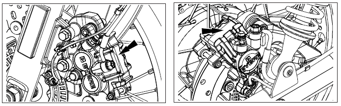
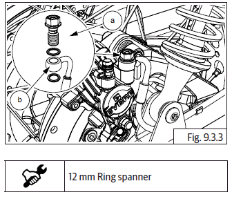
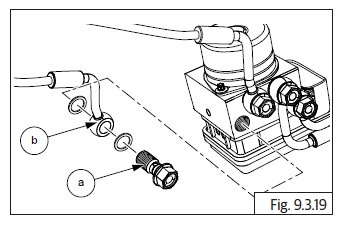
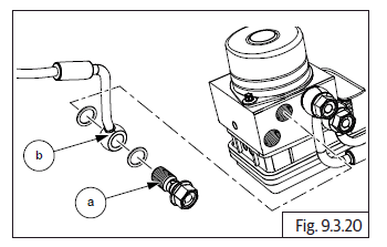
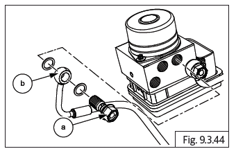
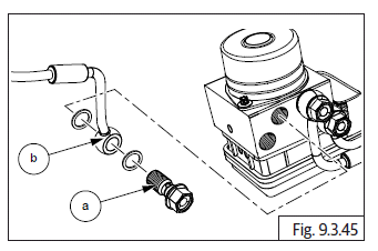
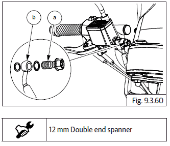
- Loosen and remove banjo bolt (a) and disconnect hose (b) from front caliper on front fork LH.
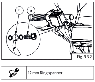
- Loosen and remove banjo bolt (a) and disconnect hose (b) from front master cylinder on handlebar RH.
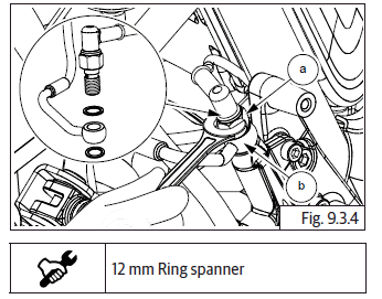
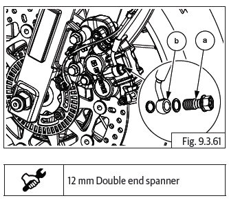
- Loosen and remove banjo bolt (a) and disconnect hose (b) from rear caliper from rear wheel RH.
- Loosen and remove banjo bolt (a) and disconnect hose (b) from rear master cylinder assembly.
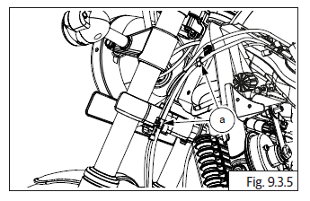
- Remove brake hose mounting clamps front (a) from frame.
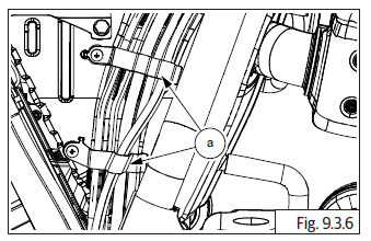
- Remove brake hose mounting clamp rear (a) from air filter box RH.
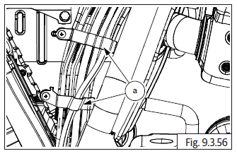
- Disconnect holding straps (a) of the brake hoses to the frame/fork end/swing arm.
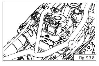
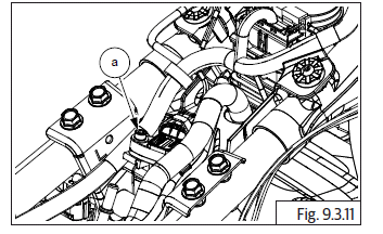
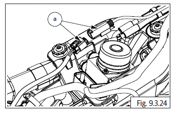
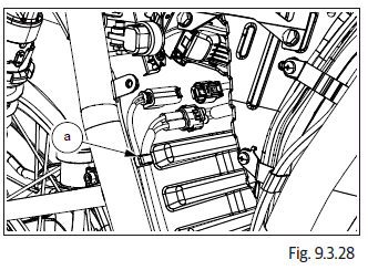
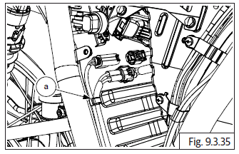
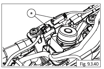
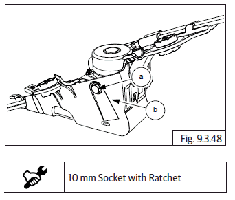
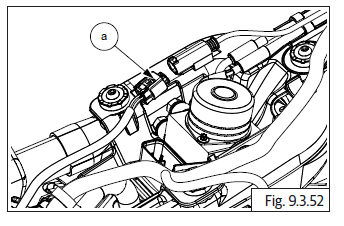
- Disconnect ABS modulator electrical connector (a) from ECU.
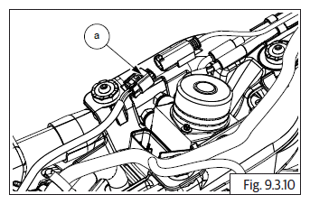
- Remove strap holding main harness (a) to ABS housing bracket and move harness away from the bracket.
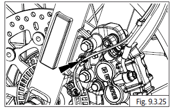
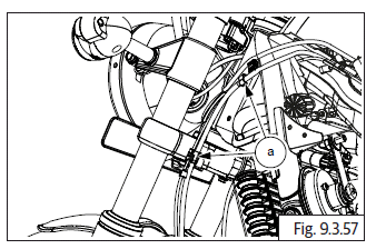
- Disconnect front wheel speed sensor wiring connector (a) from harness.
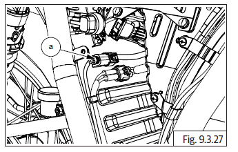
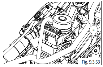
- Disconnect MAP sensor connection and loosen and remove MAP sensor mounting bolt (a) from modulator bracket.
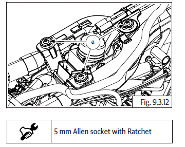
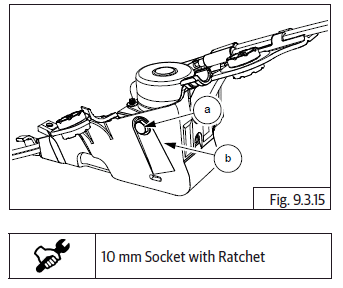
- Loosen and remove 3 Nos. mushroom head screws (M6) (a) holding ABS modulator mounting bracket from frame.
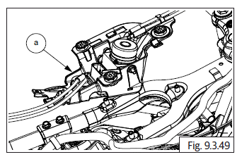
- Ensure all 4 Nos. brake hoses are free to be removed along with modulator from frame.
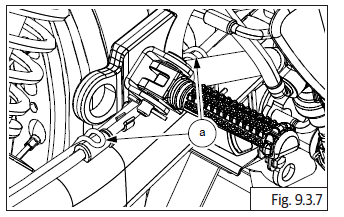
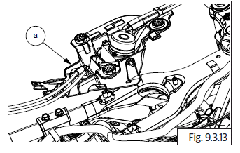
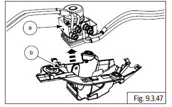
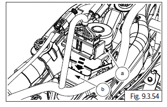
- Gently pull out modulator (a) along with bracket and 4 Nos. hoses from frame and remove.
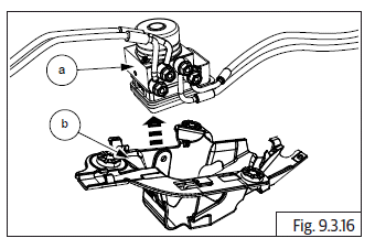
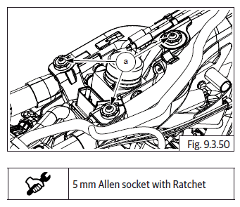
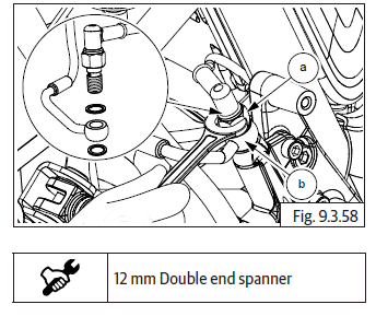
- Loosen and remove hex bolt (M6) (a) at the rear side of the bracket (b).
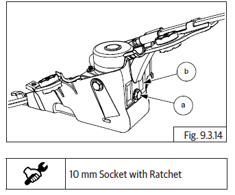
- Loosen and remove hex bolt (M6) (a) at the LH side of bracket (b).
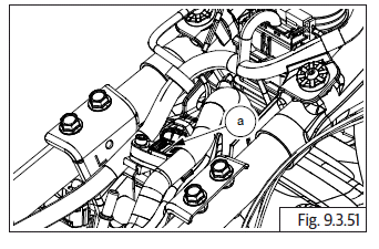
- Separate the ABS modulator (a) from bracket (b) and remove along with the 4 Nos. brake hoses.
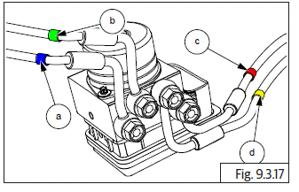
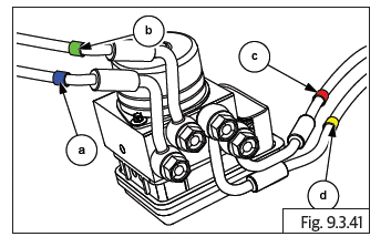
- Brake hose color tags:
- BLUE - Front Master Cylinder Assembly
- GREEN - Front Brake Caliper
- RED - Rear Brake Caliper
- YELLOW - Rear Master Cylinder Assembly
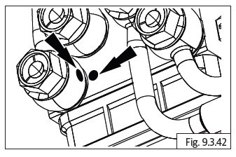
- Reference mark to be created during dismantling for ease of assembly.
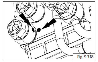
- Repeat the above process to other brake hoses.
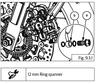
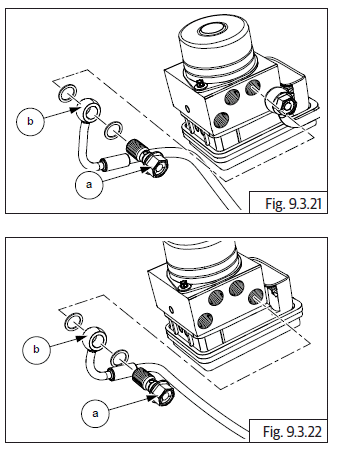
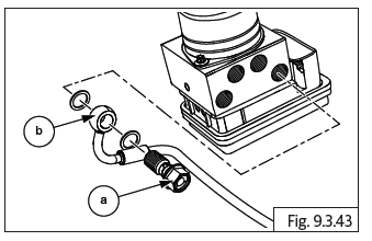
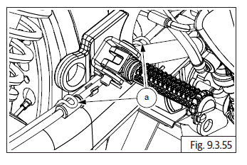
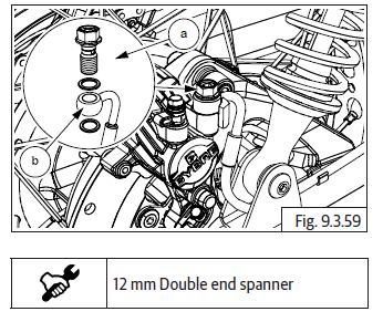
- Support modulator suitably on a work table, loosen and remove 4 Nos. banjo bolts (a) along with washers from modulator to remove brake hoses (b).
- Remove 4 Nos. brake hoses from modulator.
Do's & Don'ts
- DO NOT interchange ABS unit/ECU from one motorcycle to another.
- Whenever the modulator is removed from the motorcycle, please ensure it is stored upright with the ports facing upwards.
- Store the ECU in a cool and dry place.
- Store the ECU away from any magnetic forces as it will affect the ECU program software and damage the ECU.
- DO NOT allow moisture to affect ECU..
Wheel Speed Sensor - Front
- Ensure Ignition switch and Engine stop switch are in OFF position.
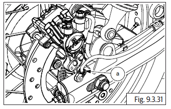
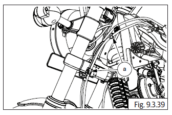
- Release sensor coupler wire from the brake hose clip on fork end LH and from the bracket on the frame.
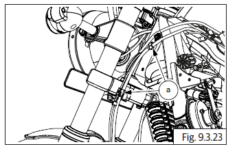
- Disconnect sensor coupler (a) from harness near ABS modulator bracket.
- Remove sensor coupler wire from clip on fork end LH.
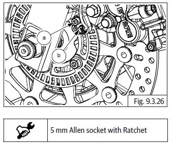
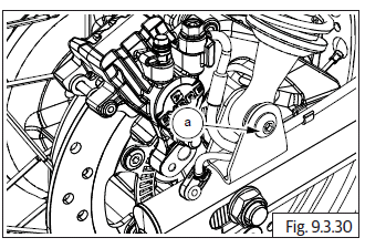
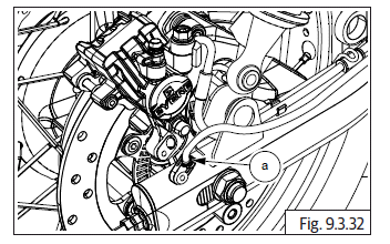
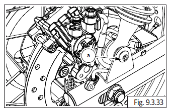
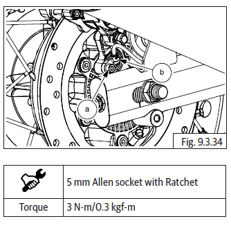
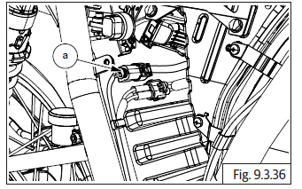
- Loosen and remove hex socket head bolt (M6) (a) holding sensor (b) to fork end LH.
- Gently pull out sensor from fork end LH.
Wheel Speed Sensor - Rear
- Ensure Ignition switch and Engine stop switch are in OFF position.
- Remove the following parts:
- Side panel RH.
- Rider seat.
- Disconnect battery terminals and remove battery from battery carrier.
- Disconnect sensor coupler (a) from harness near rollover sensor.
- Release sensor coupler wire from the routing in mudguard (a) and brake hose clip on swing arm RH.
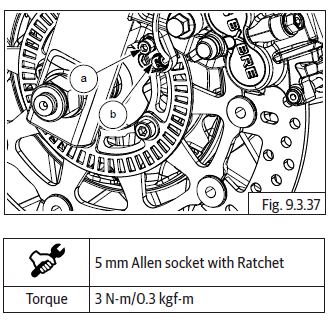
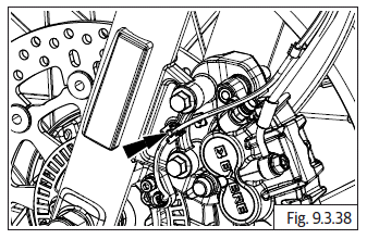
- Loosen and remove hex flange head bolt (M6) (a) holding sensor (b) to rear wheel caliper bracket top.
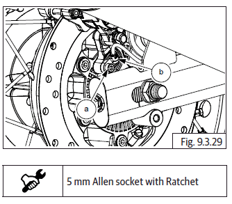
- Loosen and remove rear shock absorber RH, bottom mounting hex socket head bolt (a) and release shock absorber from swing arm.
- Gently pull out sensor (a) from rear wheel caliper bracket top.
Toner Ring - Front
- Refer front wheel removal.
Toner Ring - Rear
- Refer rear wheel removal.
Assembly
Toner Ring - Front
- Refer front wheel assembly.
Toner Ring - Rear
- Refer rear wheel assembly.
Wheel Speed Sensor - Rear
- Gently locate sensor (a) into rear wheel caliper bracket top.
- Locate and tighten rear shock absorber RH, bottom mounting hex socket head bolt (a) and assemble shock absorber into swing arm.
- Locate and tighten hex flange head bolt (M6) (a) holding sensor (b) to rear wheel caliper bracket top.
- Locate sensor coupler wire into the routing in mudguard (a) and brake hose clip on swing arm RH.
- Connect sensor coupler (a) into harness near rollover sensor.
- Locate battery into battery tray and connect battery terminals.
- Assemble the following
- Side panel RH.
- Rider seat.
Wheel Speed Sensor - Front
- Gently locate sensor onto fork end LH.
- Locate and tighten hex flange bolt (M6) (a) holding sensor (b) to fork end LH.
- Locate sensor coupler wire into clip on fork end LH.
- Locate sensor coupler wire mounting clamps front (a) into frame.
- Connect sensor coupler (a) into harness near ABS modulator bracket.
WARNING DO NOT interchange ABS unit/ECU from one motorcycle to another.
Modulator
- Brake hose color tags:
- BLUE - Front Master Cylinder Assembly
- GREEN - Front Brake Caliper
- RED - Rear Brake Caliper
- YELLOW - Rear Master Cylinder Assembly
- Ensure the sequence of the hoses is as per the color tags shown below.
- Locate 4 Nos. brake hoses into modulator.
- Support modulator suitably on a work table, keeping the color tags in mind, locate and tighten 4 Nos. banjo bolts (a) along with washers into modulator to fix brake hoses (b).
- Ensure the reference marks to align properly.
- Repeat the above process to other brake hoses.
- RED - Modulator to rear brake caliper hose.
- YELLOW - Modulator to rear master cylinder assembly hose.
- GREEN - Modulator to front brake caliper hose.
- BLUE - Modulator to front master cylinder assembly hose.
- Locate the ABS modulator (a) into bracket (b) along with 4 Nos. brake hoses.
- Locate and tighten hex bolt (M6) (a) at the LH side of bracket (b).
- Gently locate and assemble modulator (a) along with bracket and 4 Nos. hoses (b) into frame.
- Loosen and remove 3 Nos. mushroom head screws (M6) (a) holding ABS modulator mounting bracket to frame.
- Ensure all 4 Nos. brake hoses are free to be removed along with modulator from frame.
- Locate and assemble MAP sensor (a) into modulator bracket and connect MAP sensor connection.
- Connect front wheel speed sensor wiring connector (a) into harness.
- Move harness towards the bracket and locate strap holding main harness (a) to ABS housing bracket.
- Connect ABS modulator electrical connector (a) into engine control unit (ECU) (b).
- Connect holding straps (a) of the brake hoses to the frame/fork end/swing arm.
- Locate brake hose mounting clamp rear (a) into air filter box RH.
- Locate brake hose mounting clamps front (a) into frame.
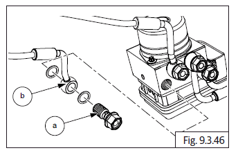
- Locate and assemble banjo bolt (a) and connect hose (b) into rear master cylinder assembly.
- Locate and assemble banjo bolt (a) and connect hose (b) into rear caliper from rear wheel RH.
- Locate and assemble banjo bolt (a) and connect hose (b) into front master cylinder on handlebar RH.
- Locate and assemble banjo bolt (a) and connect hose (b) into front caliper on front fork LH.
- Assemble the following parts:
- Fuel tank assembly.
- Rider seat.
- Side panel RH.
CAUTION After assembly of all aggregates, ensure the following:
- Fuel is refilled/top up into fuel tank.
- Fuel feed and return hoses are properly connected into the fuel rail.
- Wiring couplers to fuel pump and low fuel sensors are properly connected.
- EVAP hose pipes are properly connected.
WARNING Gasoline is extremely flammable and highly explosive. Improper handling can lead to fatal accident or serious injury.
See also:
 Royal Enfield Interceptor 650 - Service manual > Brake - Front/Rear
Brake - Front Brake - Rear
Royal Enfield Interceptor 650 - Service manual > Preparation (Front/Rear Disc Brake)
Preparation (Front Disc Brake) Use a Philips screwdriver to loosen and remove the screws of the front disc brake master cylinder. Remove the cap, and Diaphragm Plate with diaphragm. Remove the dust cap and place the suitable ring spanner on the bleeding nipple and attach a Vinyl Pipe ( transparent). Thereafter, take a Clean glass / Plastic container (transparent) with fresh brake fluid, and dip the other end of the vinyl pipe (transparent) in it (make sure that the vinyl pipe is always submerged in the fluid during the bleeding process). Connect the DOL tool switch "ON" the ignition.
 Rider's Manual BMW R 1250 GS GSA
 Owner's Manual Harley-Davidson Sportster XL1200X Forty-Eight
 Owner's Manual Honda CBR650R
 Service manual Honda CBR650
 Owner's Manual Honda PCX125
 Owner's Manual Kawasaki Z1000SX
 Service manual Kawasaki Z1000SX
 Owner's Manual Lexmoto Echo
 Owner's Manual Royal Enfield Interceptor 650
 Service manual Royal Enfield Interceptor 650
 Owner's Manual Yamaha MT-07