 Royal Enfield Interceptor 650 - Service manual > Brake - Front/Rear
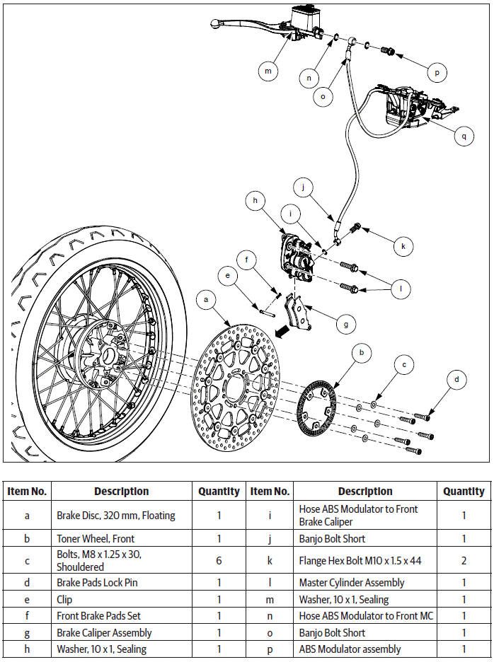
Brake - Front
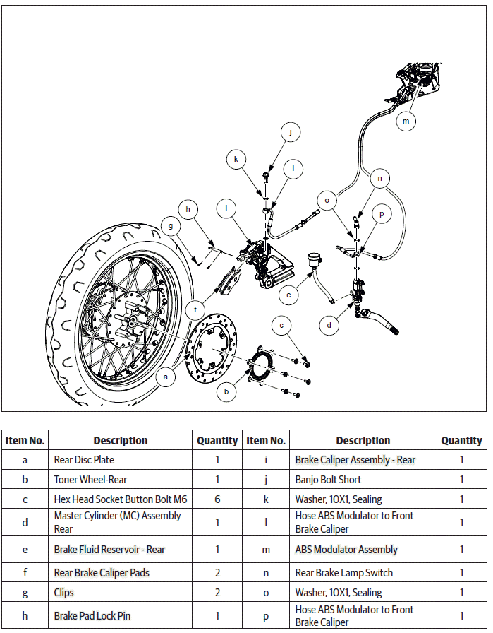
Brake - Rear
Dismantling
Brake - Front
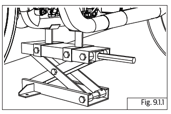
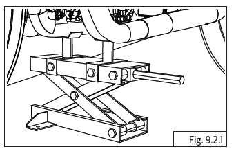
CAUTION Ensure the motorcycle is upright on a firm and flat surface.
Support motorcycle with suitable equipment below swing arm frame.
- Before dismantling brake assembly, bleed out brake fluid.
NOTE
- If brake pads are being replaced, then it is not necessary to perform system bleeding.
- Wheel should be dismantled only for brake disc plate removal.
CAUTION Whenever front brake caliper assembly is dismantled from front wheel, DO NOT depress brake lever as the piston in the caliper will move out/get misaligned.
DO NOT remove or disturb the wheel speed sensor on fork end LH.
Master Cylinder Assembly - Front
- Remove the following part:
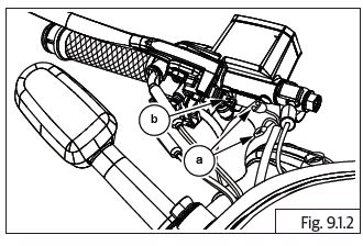
- Rear view mirror from handlebar RH.
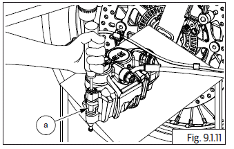
CAUTION Ensure master cylinder assembly is supported carefully while disconnecting.
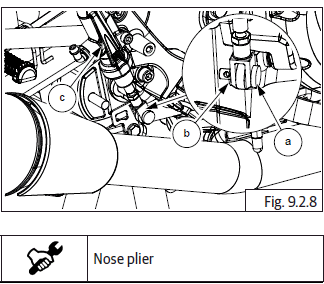
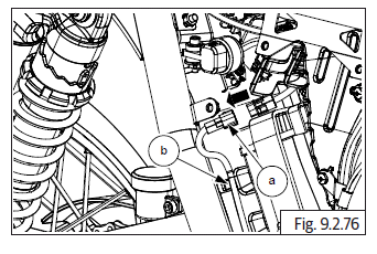
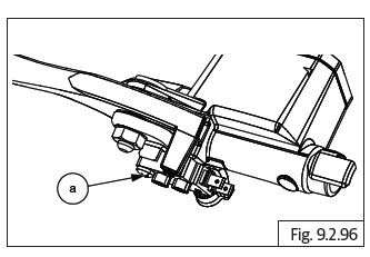
- Disconnect brake lamp switch connectors (a) from brake lamp switch (b).
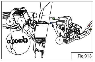
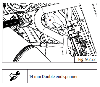
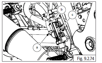
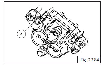
- Loosen and remove banjo bolt (a) holding the brake hose (b) to front master cylinder to ABS modulator (c).
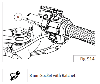
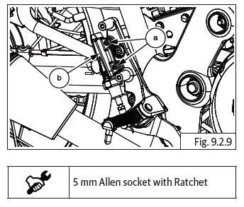
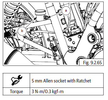
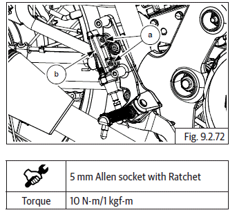
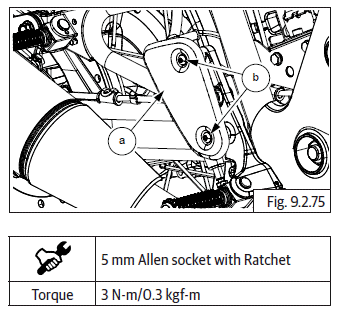
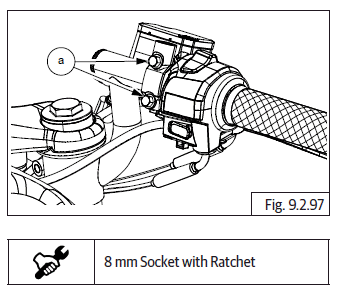
- Loosen and remove 2 Nos. Hex bolts (M5) (a) along with washers from clamp and remove master cylinder assembly from handlebar RH.
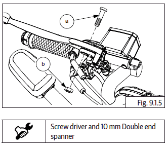
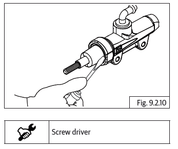
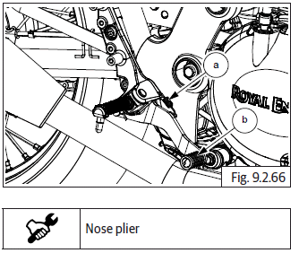
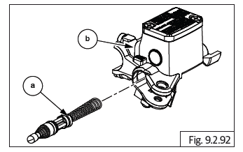
- Hold screw (a) at the top of brake lever, loosen and remove hex nut (M6) (b) at the bottom.
- Unscrew and remove top screw holding brake lever to master cylinder and remove brake lever.
Dismantling Master Cylinder Front
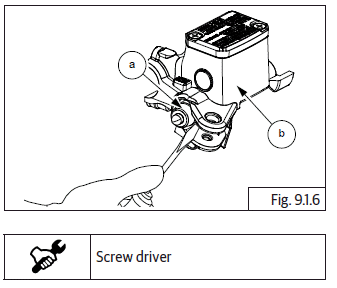
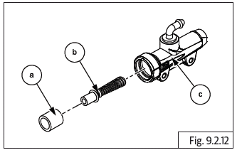
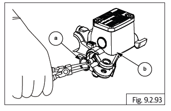
- Remove boot (a) from the master cylinder assembly (b).
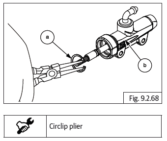
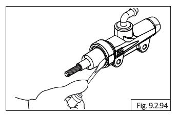
- Remove circlip (a) from the master cylinder assembly (b).
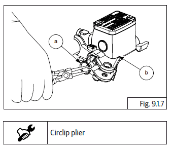
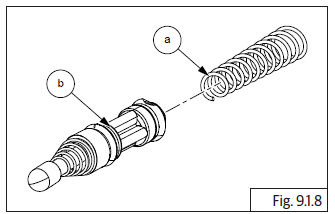
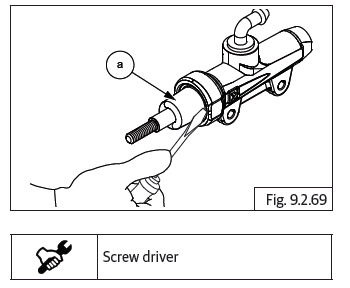
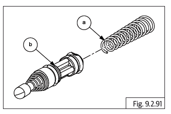
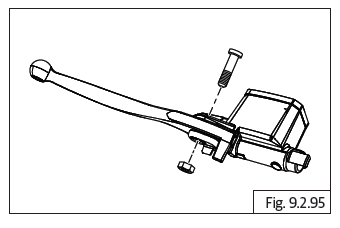
- Remove the conical spring (piston compression spring) (a) from piston (b).
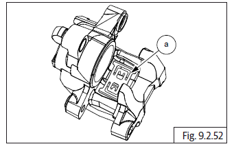
Brake Caliper - Front
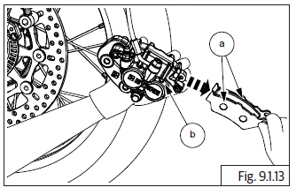
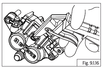
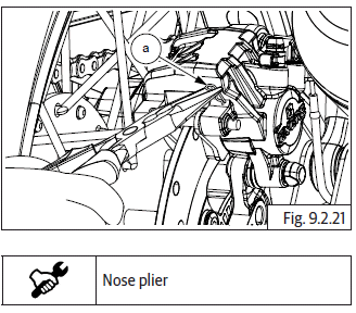
- Gently remove hose from caliper assembly.
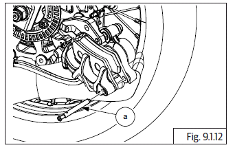
- Support the front brake caliper assembly suitably.
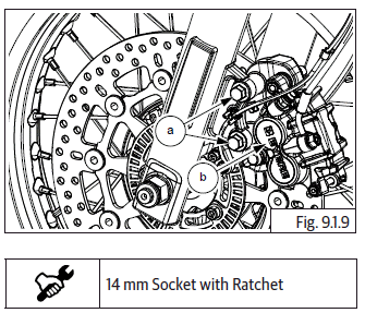
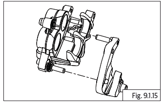
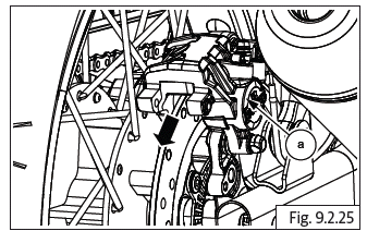
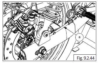
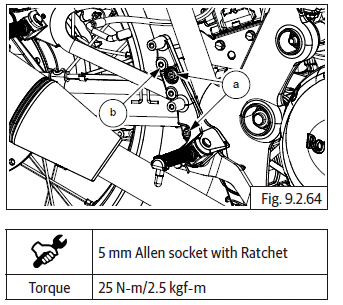
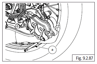
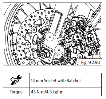
- Loosen and remove upper and lower Hex flange head bolts (M10) (a) to remove front brake caliper assembly (b) from LH fork.
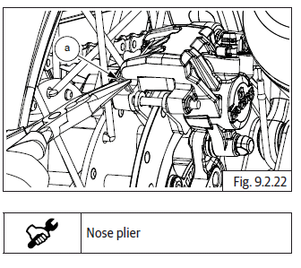
- Gently slide out front brake caliper assembly from front LH fork.
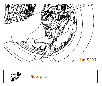
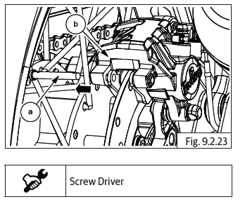
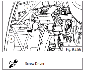
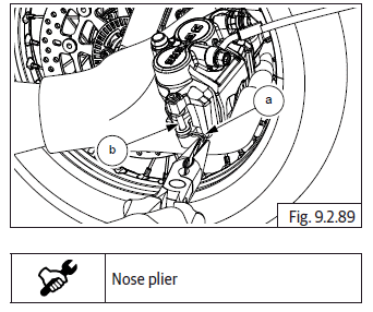
- Remove brake pad lock clip (a) from brake caliper assembly (b).
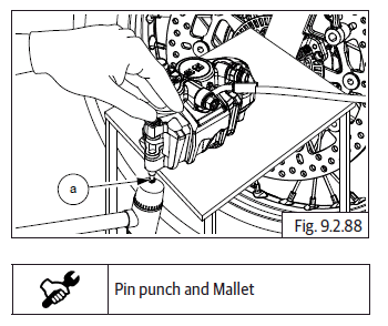
- Suitably support caliper and correctly tap brake pad pin (a) from inner side to outside.
- Once pin (a) is free, gently pull out pin from brake caliper.
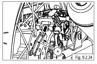
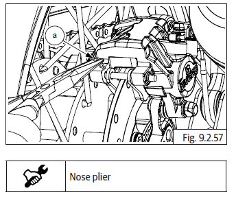
- Slide out and remove brake pads (a) from brake caliper front (b).
Dismantling Front Brake Caliper
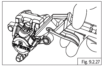
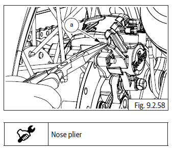
- Remove the pad tensioner spring plate (a).
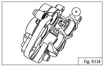
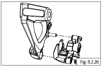
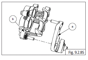
- Remove mounting bracket from caliper assembly.
- Remove the bellow and boot.
- Position caliper body with the pistons down and apply small squirts of air pressure to fluid inlet hole to remove pistons.
CAUTION Do not use high pressure air or bring the nozzle too close to the inlet. Place a shop towel over the pistons to prevent the pistons from becoming projectiles. Push the dust seals and piston seals in and lift them out using a blunt tool. Care should be taken to avoid any damages on the bore of the sliding surface.
Enough care should be taken to avoid damages of the piston OD while servicing/handling. Remove the bleed screw.
Brake Disc - Front
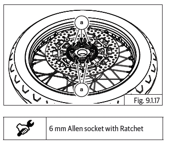
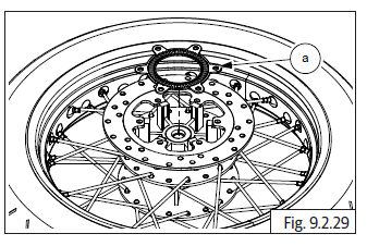
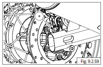
- Remove front wheel.
- Ensure wheel assembly is placed on a flat surface with disc plate facing upwards.
CAUTION Ensure wheel hub does not get damaged.
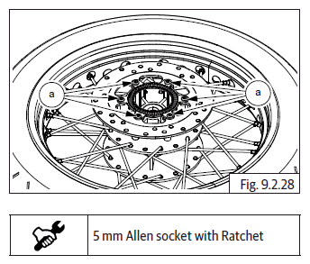
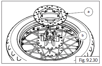
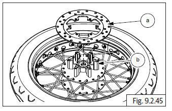
- Loosen and remove 6 Nos. Hex socket head bolts (M8) (a) from wheel LH in criss cross pattern holding toner ring and brake disc to hub.
WARNING DO NOT place/store the wheel with disc facing downward. It will cause bends and damages and change warpage.
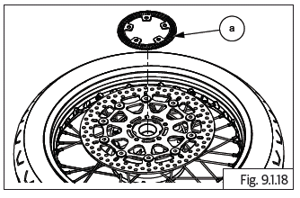
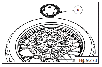
- Remove toner wheel (a) and keep it aside safely.
CAUTION Avoid any bends or damages to the toner wheel as it will have serious effects on ABS performance.
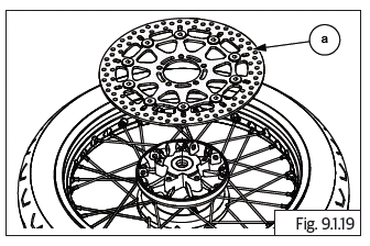
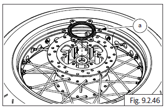
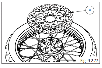
- Remove front brake disc (a).
CAUTION Avoid any bends or damages to the brake disc as it will have serious effects on braking efficiency and will lead to juddering.
Brake - Rear
CAUTION Ensure the motorcycle is upright on a firm and flat surface.
Support motorcycle with suitable equipment below swing arm frame.
Master Cylinder Assembly - Rear
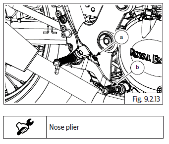
- Disconnect brake lamp connector (a) from main wiring harness on motorcycle RH.
- Remove wire from rear mudguard infill cover (b).
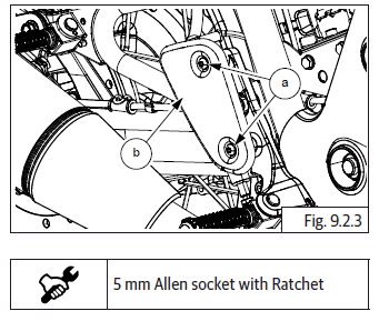
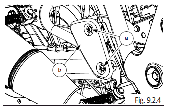
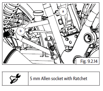
- Loosen and remove 2 Nos. button socket head bolts (M6) (a) to remove master cylinder guard (b) from frame.
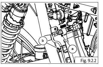
- Remove brake hose clip (a) from brake fluid reservoir (b) located near master cylinder assembly (c).
- Collect brake fluid in container (a).
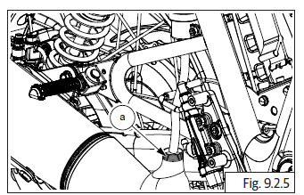
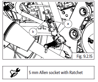
- Loosen and remove brake lamp switch nut (M8) (a).
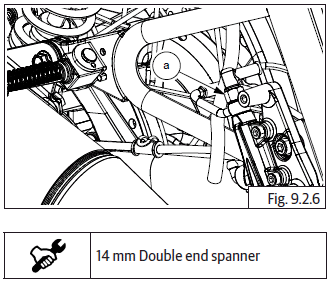
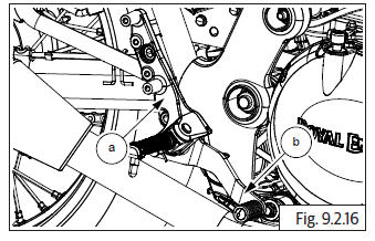
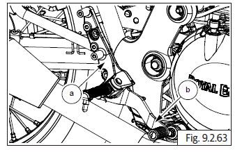
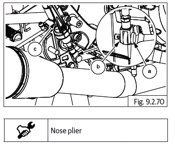
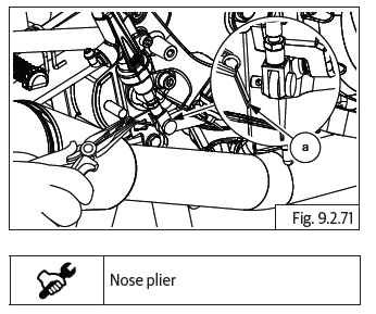
- Remove split pin (a) from clevis pin located at the bottom of master cylinder assembly.
- Remove clevis pin (a) along with washer (b) from bottom of master cylinder assembly (c).
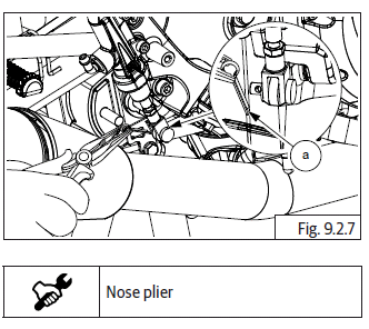
- Loosen and remove 2 Nos. Hex socket head bolts (M6) (a) to detach master cylinder assembly (b) from bracket.
Dismantling Rear Brake Master Cylinder
- Remove protective rubber boot from master cylinder.
- Remove (a) circlip from the master cylinder body (b) slowly and carefully.

- Gently pull out bush (a) with piston (b), seals, spring guide and conical spring from master cylinder housing (c).
CAUTION Do not use any sharp tool to pull out the piston from the master cylinder. Pull out gently with minimum force.
Rear Brake Pedal
- Remove brake pedal spring (a) located on brake pedal (b).
- Loosen and remove Hex socket bolt M6 (a) to remove fluid reservoir (b).
- Loosen and remove 2 Nos. Hex socket bolt (M6) (a) to remove master cylinder bracket (b) from motorcycle.
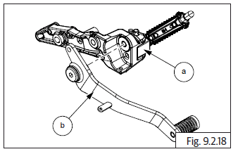
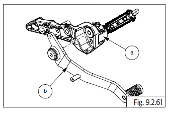
- Remove master cylinder bracket (a) along with brake pedal (b) from motorcycle.
- Loosen and remove Hex socket bolt (M8) (a) to detach master cylinder bracket from brake pedal (b).
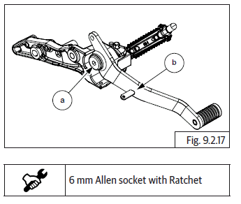
- Separate master cylinder bracket (a) and brake pedal (b).
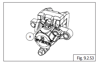
Brake Caliper Assembly - Rear
- Remove the following:
- Swing arm bolt, spindle and chain adjuster assembly from rear wheel.
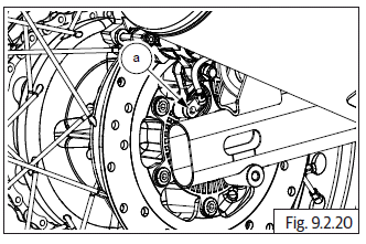
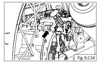
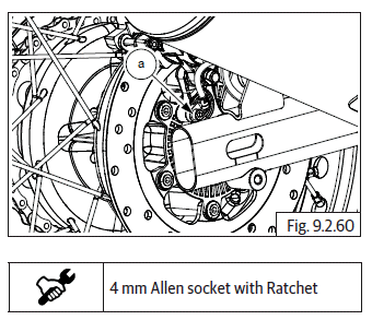
- Loosen and remove Hex socket head screw (M6) (a) located below brake caliper on RH rear wheel.
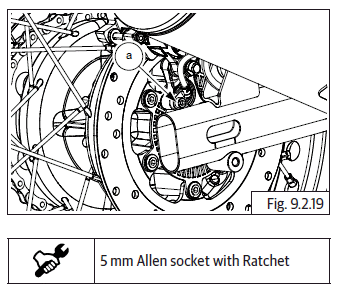
- Gently remove rear wheel speed sensor ABS (a) from rear wheel hub.
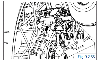
- Remove brake pad outer clip (a) from brake pad lock pin.
- Remove brake pad inner clip (a) from brake pad lock pin.
- Remove brake pad lock pin (a) from brake caliper (b).
- Slide out and remove brake pads (a) from brake caliper.
- Slide out and remove brake caliper (a) with holder.
Dismantling Rear Brake Caliper
- Separate the mounting bracket from the caliper assembly by gently pulling them apart.
- Position caliper body with pistons down and apply small squirts of air pressure to the fluid inlet hole to remove pistons.
CAUTION DO NOT use high pressure air or bring the nozzle too close to the inlet. Place a shop towel over the pistons to prevent the pistons from becoming projectiles. Push the dust seals and piston seals in and lift them out using a blunt tool. Care should be taken to avoid any damage on the bore of the sliding surface.
Enough care should be taken to avoid damages of the piston OD while servicing/handling. Remove the bleed Screw.
Brake Disc - Rear
- Remove drive chain and rear wheel from swing arm.
- Loosen and remove 6 Nos. Hex head button socket screws (M6) (a) from rear wheel disc hub RH (b).
- Remove ABS toner wheel (a) from rear wheel hub RH.
- Remove rear disc plate (a) from rear wheel hub RH and keep aside safely.
Inspection
- Inspect for rust, deep scoring, any foreign materials, burn marks crack in the mounting location of front and rear brake discs.
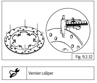
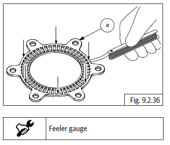
- Inspect front and rear brake disc thickness and run-out. Measure depth at points where scoring is found on the discs and replace if there is excess wear. (Need to confirm).
- Also measure thickness at the points indicated in the illustration and replace disc if out of specifications.
Front brake disc.
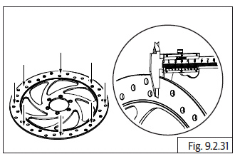
Rear brake disc.
- Place brake disc rotor on a flat surface and inspect warpage. Replace if it is out of specifications.
Front brake disc.
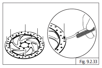
Rear brake disc.
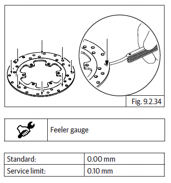
- Inspect and replace toner wheel front if there are any damages or bends.
- Place toner wheel front on a flat surface and check warpage. Replace if out of specifications.
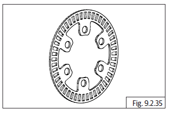
- Inspect and replaces toner wheel rear ABS (a) if there are any damages bends.
- Place ABS toner wheel on a flat surface and check warpage. Replace if out of specifications.
- After assembly of brake disc (a) into front wheel, insert spindle into rim, fix on wheel balance frame (b) and rotate rim to check the disc run-out with dial gauge (c). Ensure run-out is within specified limits.
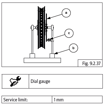
CAUTION Run-out of brake disc should be checked only when brake disc is assembled on wheel hub.
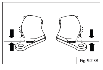
- Inspect brake pad thickness- front and rear. Replace if worn-out.
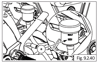
- Check brake fluid level and top up if line is below 'MIN' level (a).
Front
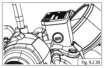
Rear
CAUTION DO NOT mix DOT 4 and other brake fluids together.
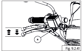
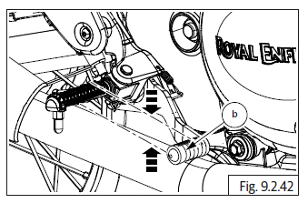
- Inspect brake lever front (a) free play and brake pedal rear (b) free play. If free play is spongy, check brake pads for wear or tear and replace and follow brake bleeding procedure.
Front
Rear
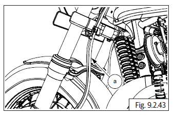
- Inspect and replace front and rear brake hoses (a) if they have any cracks, leakages or damages.
Front
Rear
Assembly
Brake - Rear
Brake Disc - Rear
- Assemble rear disc plate (a) into rear wheel hub RH (b).
- Assemble ABS toner (a) into rear wheel hub RH.
- Insert and tighten 6 Nos. Hex head button socket screws (M6) (a) into rear wheel disc hub RH.
- Assemble drive chain and rear wheel into swing arms.
Brake Caliper Assembly - Rear
Assembling Rear Brake Caliper
- Coat fresh brake fluid on new dust seals and piston seals.
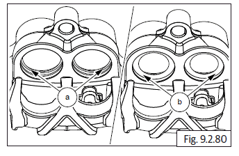
- Install piston seals in the inner groove (a) and dust seals in the outer groove (b) in the bore in caliper assembly.
- Coat the caliper cylinder and piston with fresh brake fluid.
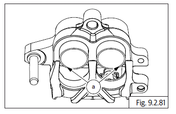
- Insert the closed end of the piston (a) into the caliper bore and gently press it into caliper fully till the open ends of the piston are flush with the caliper bore outer edge
CAUTION DO NOT apply force while assembling the piston into the caliper. Press only with minimal hand pressure.
- Assemble the rubber grommets (a) on the bracket mounting area of the caliper.
- Locate bracket (a) on the caliper (b) and gently press caliper into bracket fully.
- Install the pad tension spring plate (a) in the Caliper body.
- Assemble Bleed screw (a) with the dust cap on the caliper body.
- Gently locate brake caliper (a) with holder onto brake disc.
Rear Brake Pads in Wheel Caliper
- Gently locate brake pads (a) into brake caliper.
- Locate brake pad lock pin (a) into brake caliper (b).
- Install brake pad inner clip (a) into brake pad lock pin.
- Install brake pad inner clip (a) into brake pad lock pin.
- Gently assemble rear wheel speed sensor ABS (a) into rear wheel hub.
- Locate and tighten Hex socket head screw (M5) (a) located below brake caliper on rear wheel RH.
- Assemble swing arm bolt, spindle and chain adjuster assembly into rear wheel.
Master Cylinder Assembly - Rear
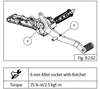
- Locate master cylinder bracket (a) over brake pedal (b).
- Insert and tighten Hex socket bolt (M8) (a) to fix master cylinder bracket on brake pedal (b).
- Assemble master cylinder bracket (a) along with brake pedal (b) into motorcycle.
- Insert and tighten 2 Nos. Hex socket bolts (M6) (a) to fix master cylinder bracket (b) into motorcycle.
- Locate fluid reservoir on frame.
- Insert and tighten Hex socket bolt (M6) (a) to fix fluid reservoir (b).
- Assemble brake pedal spring (a) on brake pedal (b).
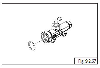
- Locate new O-ring inside the master cylinder bore.
CAUTION DO NOT use any sharp tool to assemble the O-ring or piston in the master cylinder.
- Assemble spring guide on the small end of spring.
- Locate peg on piston, on spring guide.
- Locate large bush over the piston.
- Insert large end of the spring along with the piston and guide bush into the master cylinder bore and hold it in compressed position inside master cylinder.
- Assemble Circlip (a) in the master cylinder body (b) and ensure it is locked properly in the groove.
- Assemble the protective rubber boot (a) on the master cylinder.
- Insert clevis pin (a) and washer (b) from bottom of master cylinder assembly (c).
- Insert split pin (a) to clevis pin located at the bottom of master cylinder assembly then expand the split pin.
- Locate master cylinder assembly into master cylinder bracket.
- Insert and tighten 2 Nos. Hex socket bolts (M6) (a) to fix master cylinder assembly (b) into master cylinder bracket.
- Insert and tighten brake lamp switch nut (M8) (a) into master cylinder assembly.
- Assemble brake hose clip (a) into brake fluid reservoir (b) near master cylinder assembly (c).
- Locate master cylinder guard (a) onto frame and insert and tighten 2 Nos. button socket head bolts (M6) (b).
- Connect brake lamp coupler (a) to main wiring harness on motorcycle RH.
Brake - Front
Brake Disc - Front
- Locate front brake disc (a) on front wheel hub and disc facing outward. Ensure six mounting holes are correctly aligned.
- Position toner wheel (a) onto front disc and ensure mounting holes are correctly aligned.
- If bolts are pre-coated bolts replace with new ones.
- If they are non-coated, clean threads and wait for few minutes and apply thread sealant.
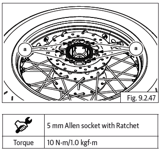
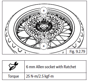
- Insert 6 Nos. Hex socket head bolts (M8) (a) into brake disc LH and tighten in criss cross pattern to specified torque.
- Assemble front wheel into front fork assembly.
Brake Caliper - Front
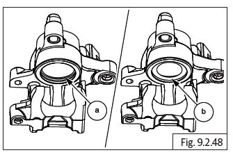
- Coat fresh brake fluid on new dust seals and piston seals.
- Install piston seals in inner groove (a) and dust seals in outer groove (b) in the bore in caliper assembly.
- Coat the caliper cylinders and pistons with fresh brake fluid.
- Insert closed end of the pistons into caliper bores and gently press it into caliper fully till open ends of the piston (a) are flush with caliper bore outer edge.
NOTE
- Do not apply force while assembling the pistons into the caliper. Press only with minimal hand pressure. Assemble pistons one at a time into the caliper.
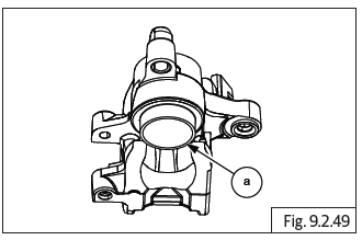
- Smear fresh brake fluid on the caliper boot and bellow and assemble them on the caliper body.
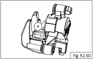
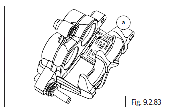
- Install pad tension spring plate (a) in caliper body.
- Assemble bleeder valve (a) with dust cap on the caliper body.
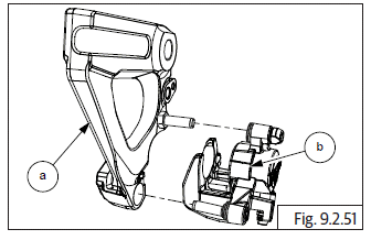
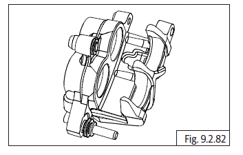
- Assemble the mounting bracket (a) on caliper body (b).
- Slide in and assemble brake pads (a) into brake caliper (b).
- Lubricate and insert brake pad pin (a) into caliper.
- Suitably support caliper and correctly tap brake pad pin (a) from outside to inside.
- Assemble brake pad lock clip (a) into the brake pad pin (b).
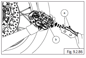
- Support and hold the front brake caliper assembly suitably onto the front LH fork.
- Locate and tighten upper and lower Hex flange head bolts (M10) (a) to fix front brake caliper assembly (b) to LH fork.
- Gently install hose into caliper assembly.
Master cylinder - Front
- Locate the conical spring (a) on the piston (b).
- Smear piston seals and cylinder bore with fresh brake fluid and assemble piston (a) subassembly into master cylinder (b) by gently pushing it into the bore.
- Compress and assemble circlip (a) into groove of master cylinder (b).
CAUTION DO NOT use tools with sharp ends.
Ensure circlip is locked properly after assemble.
- Assemble the rubber Boot.
- Apply silicon grease on the lever pivot hole and on the Piston surface.
- Position brake lever inside the bracket, locate pivot screw from the top and tighten to bracket.
- Assemble lock nut below and tighten.
- Assemble the Brake Switch on the bracket.
- Locate master cylinder assembly on handlebar RH and locate clamp over cylinder.
- Locate and tighten 2 Nos. Hex flange head bolt (M5) (a) into clamp and fix the master cylinder assembly.
- Refill fluid, inspect and diagnose if there are any leakages.
See also:
 Royal Enfield Interceptor 650 - Service manual > Anti-lock Braking System (ABS)
Working Principle The Royal Enfield Continental GT 650 twin and Interceptor 650 twin motorcycles are equipped with the state of the art Anti-Lock Braking System (ABS).
 Rider's Manual BMW R 1250 GS GSA
 Owner's Manual Harley-Davidson Sportster XL1200X Forty-Eight
 Owner's Manual Honda CBR650R
 Service manual Honda CBR650
 Owner's Manual Honda PCX125
 Owner's Manual Kawasaki Z1000SX
 Service manual Kawasaki Z1000SX
 Owner's Manual Lexmoto Echo
 Owner's Manual Royal Enfield Interceptor 650
 Service manual Royal Enfield Interceptor 650
 Owner's Manual Yamaha MT-07