 Royal Enfield Interceptor 650 - Owner's Manual > Battery and maintenance
- The Motorcycle is provided with 12V - 12 Ah battery.
- The battery must be periodically checked for cleanliness and corrosion free terminals.
NOTE
The poor contact or loose fitment of battery terminals may cause ECU failure.
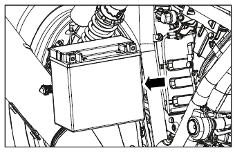
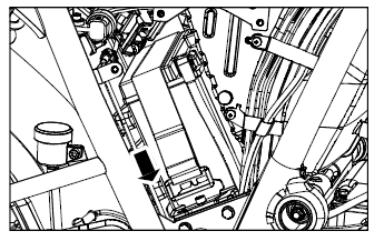
DISMANTLING
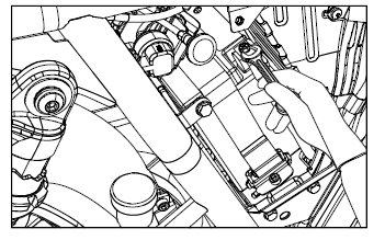
- Switch "OFF" the engine and remove ignition key from the key barrel.
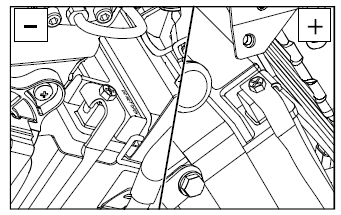
- Disconnect battery negative (- ve) terminal bolt.
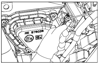
- Remove 3 Nos. Hex head bolts from tool box to access the battery.
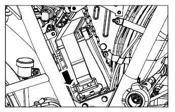
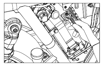
- Disconnect battery positive (+ve) terminal from battery.
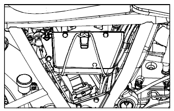
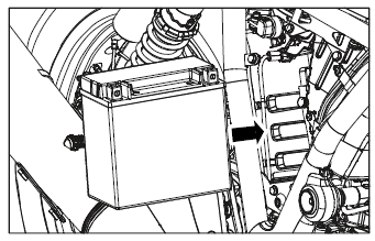
- Pull battery strap (belt) downwards and release strap lock from battery strap bracket.
- Loosen and remove hex flange head screw from battery strap bracket.
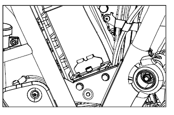
- Remove battery strap bracket from battery tray.
- Remove battery from tray.
WARNING
Always disconnect the black negative (-ve) battery cable first and then the red positive (+ve) cable while removing the battery connections.
NOTE
For checking the battery voltage contact Royal Enfield Authorised Service Centre or battery service centre.
ASSEMBLY
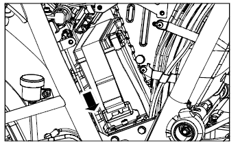
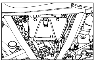
- Assemble battery in to tray.
- Place battery strap bracket into battery tray.
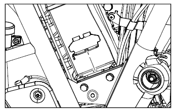
- Locate and tighten flanged head screw into battery strap bracket.
- Pull battery strap (belt) downwards to fix strap lock into battery strap bracket.
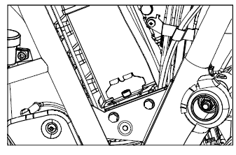
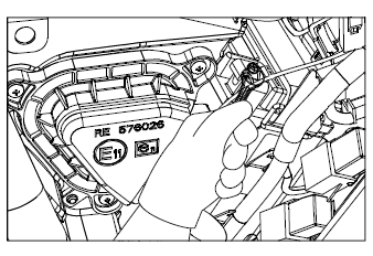
- Connect battery red positive (+ve) terminal bolt.
- Locate and tighten 3 nos. hex head bolts into tool holder.
- Connect black battery negative (-ve) terminal bolt.
CAUTION
Connect the black (-ve) negative terminal after connect red (+ve) positive terminal only.
NOTE
Clean the wire terminals free from corrosion and keep the terminals coated with petroleum jelly.
CAUTION
Keep the red (+ve) positive terminal and (-ve) negative terminal cables firmly connected to the respective battery terminals. Failure to do so may result in damage to the motorcycle electrical system.
See also:
 Royal Enfield Interceptor 650 - Owner's Manual > Rear wheel reassembly
Ensure that the long stepped spacer is located on the brake disc side and the short spacer is located on the sprocket side of the wheel hub firmly. Ensure that the chain adjuster are located properly inside the swing arm left and right sides. Locate caliper assembly on the tab along the swing arm right side. Locate rear wheel with the sprocket to the left side ensuring the brake disc in-between the brake pads on right side. Lift up the rear wheel and ensure that the slots in the swing arm brake caliper bracket holes in chain adjusters and the centre hole in the hub are aligned. Support rear wheel suitably and insert rear wheel spindle along the left side swing arm into the wheel hub. Ensure that the long stepped spacer is located along the brake side and the short spacer is located along the sprocket side on the wheel hub. Tap spindle gently into wheel hub slot till the threads are completely visible on the right side. Assemble the drive chain on the sprocket and ensure it is seated correctly. Check for free and smooth rotation of the rear wheel. Assemble washer and hex nut on wheel spindle on right side.
Royal Enfield Interceptor 650 - Owner's Manual > Changing electrical components
HEADLAMP BULB REPLACEMENT Loosen the rim holding screw on top and take out the head lamp dome. Disconnect electrical connections. Thumb push and remove the bulb holding clamp gently. Remove the bulb using a clean and soft cloth. Position the new bulb inside the reflector such that the three projections on the bulb align with the slot on the reflector. Refit the bulb holding clamp. Connect the electrical connections. Position head lamp dome onto the head lamp shell and tighten the mounting screw on top.
 Rider's Manual BMW R 1250 GS GSA
 Owner's Manual Harley-Davidson Sportster XL1200X Forty-Eight
 Owner's Manual Honda CBR650R
 Service manual Honda CBR650
 Owner's Manual Honda PCX125
 Owner's Manual Kawasaki Z1000SX
 Service manual Kawasaki Z1000SX
 Owner's Manual Lexmoto Echo
 Owner's Manual Royal Enfield Interceptor 650
 Service manual Royal Enfield Interceptor 650
 Owner's Manual Yamaha MT-07