 Royal Enfield Interceptor 650 - Owner's Manual > Rear wheel reassembly
- Ensure that the long stepped spacer is located on the brake disc side and the short spacer is located on the sprocket side of the wheel hub firmly.
- Ensure that the chain adjuster are located properly inside the swing arm left and right sides.
- Locate caliper assembly on the tab along the swing arm right side.
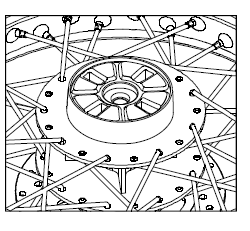
- Locate rear wheel with the sprocket to the left side ensuring the brake disc in-between the brake pads on right side.
- Lift up the rear wheel and ensure that the slots in the swing arm brake caliper bracket holes in chain adjusters and the centre hole in the hub are aligned.
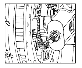
- Support rear wheel suitably and insert rear wheel spindle along the left side swing arm into the wheel hub.
- Ensure that the long stepped spacer is located along the brake side and the short spacer is located along the sprocket side on the wheel hub.
- Tap spindle gently into wheel hub slot till the threads are completely visible on the right side.
- Assemble the drive chain on the sprocket and ensure it is seated correctly.
- Check for free and smooth rotation of the rear wheel.
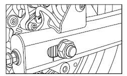
- Assemble washer and hex nut on wheel spindle on right side.
DO NOT TIGHTEN HEX NUT FULLY
- Tighten chain adjuster nuts on left and right adjuster such that the index marks are aligned correctly on both sides of the swing arm.
- Check and ensure correct chain tension and wheel alignment.
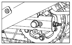
- Hold spindle firmly on left side and tighten hex nut on right side set torque to 70 Nm.
- Locate the brake hose in the clips along the swing arm right side.
- Check rear brake for proper operating efficiency.
CAUTION
Please exercise utmost caution while reassembling the rear wheel on the motorcycle.
Please ensure the wheel is fitted correctly before attempting to ride the motorcycle.
Failure to do so will result in poor performance of motorcycle which may lead to an accident causing injury to you / other road users and may lead to loss of life.
CLUTCH CABLE FREE PLAY INSPECTION/ADJUSTMENT
- Clutch cable free play, plays a major role in clutch life & it is recommended to adjust whenever required for good clutch life.
CLUTCH LEVER FREE PLAY SPECIFICATION
- Check/adjust free play 2.5 to 3 mm at clutch lever pivot when handlebar is at LH condition.
- Ensure if the free play is 2.5 - 5 mm when handle bar is at center condition.
For adjustment follow below procedure:
NOTE
Clutch lever to be actuated 3 times before any measurement.
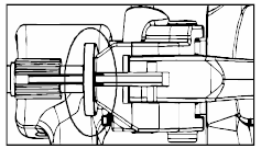
MINOR ADJUSTMENT - CLUTCH CABLE LEVER END
- Minor adjustment of free play can be done at clutch cable lever end Loosen the cable outer lock nut.
- Turn the nut clockwise to reduce the play or anticlockwise to increase the free play.
- Tighten firmly the lock nut after adjustment is done.
- After the adjustment, Check the free play and con firm for specification.
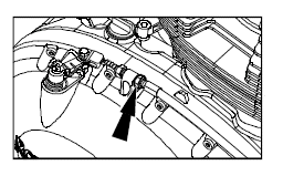
MAJOR ADJUSTMENT - CLUTCH CABLE COVER END
- Major adjustment of free play can be done at clutch cable cover end Loosen the cable outer lock nut.
- Turn the nut clockwise to reduce the play or anticlockwise to increase the free play.
- Firmly tighten two lock nuts using two spanners after adjustment is done.
- After the adjustment, Check the free play and con firm for specification.
CAUTION
- If you are not comfortable to adjust free play as per stated procedure, please visit near by service center.
- If desired free play is not achieved or there is a suspect of clutch slip - keep positive free play & reach nearest service center.
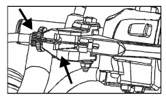
- Adjuster nut should rest properly in the threaded region. No overhanging (Ref. image)
- Clutch free play should be checked and adjusted only when the engine is cold.
- During clutch play checking, check the clutch cable for any abnormality as it is in vehicle condition. If any abnormality suspected, reach nearest service center.
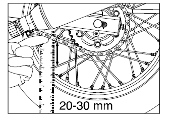
DRIVE CHAIN TENSION (Free Play 20-30 mm)
- Park motorcycle up right on a firm and at surface.
- Ensure the motorcycle is in neutral position.
- Measure the drive chain free play as shown. The drive chain free play is 20 mm to 30 mm.
1. If the drive chain free play is found to be incorrect adjust as follows:
- Loosen the axle nut of the rear wheel axle.
- Loosen the lock nut on the adjuster at both end of the swing arm.
- To reduce the free play, tighten the adjuster nut on the adjuster evenly.
- To increase the free play, loosen the adjuster nuts evenly and push the rear wheel forward.
- Check the chain for correct chain tension.
- Ensure that the index marks on the adjuster and swing arm are same on both left and right side of the swing arm.
- Hold spindle firmly to the left side and tighten rear hex nut to a torque of 70 Nm.
- Tighten the adjuster locknut using a 24mm spanner.
WARNING
Chain slackness beyond 30mm will lead to chain slippage and may also cause increased wear rates to chain and sprockets.
Maintain drive chain slackness within the specified limits at every 1000 kms interval.
Please ensure the both wheels are aligned correctly, after adjusting the chain and before tightening the rear wheel spindle nut.
See also:
 Royal Enfield Interceptor 650 - Owner's Manual > Front wheel reassembly
Remove the wooden piece / cardboard sheet placed between the brake pads. Locate speedo drive to its correct position on the right side. Locate stepped spacer to the wheel hub on left side. Insert the wheel along with speedo drive and spacer between the fork ends. Ensure the brake disc is located between the brake pads. Support front wheel at the bottom and ensure the mounting holes are aligned to insert the wheel axle along the right side fork end. Gently tap axle into wheel till the threaded portion of axle is fully visible on the left side fork end. Assemble washer and nut on axle. Hold the wheel axle firmly on right side and tighten axle nut firmly on right side to a torque of 70 Nm. Tighten pinch bolt completely on fork end to a torque of 25 Nm. Rotate wheel to check for smooth rotation. Connect the speedo wire coupler and check for proper working of speedometer. Press brake lever and check front brake efficiency.
Royal Enfield Interceptor 650 - Owner's Manual > Battery and maintenance
The Motorcycle is provided with 12V - 12 Ah battery. The battery must be periodically checked for cleanliness and corrosion free terminals.
 Rider's Manual BMW R 1250 GS GSA
 Owner's Manual Harley-Davidson Sportster XL1200X Forty-Eight
 Owner's Manual Honda CBR650R
 Service manual Honda CBR650
 Owner's Manual Honda PCX125
 Owner's Manual Kawasaki Z1000SX
 Service manual Kawasaki Z1000SX
 Owner's Manual Lexmoto Echo
 Owner's Manual Royal Enfield Interceptor 650
 Service manual Royal Enfield Interceptor 650
 Owner's Manual Yamaha MT-07