 Honda CBR650 - Service manual > Body cover
REMOVAL/INSTALLATION
Remove the seat.
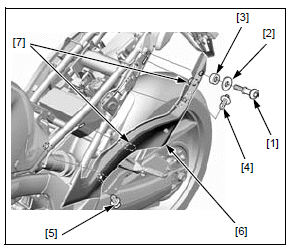
Remove the following:
- Special bolt [1]
- Washer [2]
- Collar [3]
- Trim clip (pin head) [4]
- Trim clip (screw head) [5]
Remove the body cover [6] by releasing the tabs [7] from the slots of the rear fender B.
Installation is in the reverse order of removal.
TORQUE:
Rear cowl special bolt:
22 N*m (2.2 kgf*m, 16 lbf*ft)
REAR COWL
REMOVAL/INSTALLATION
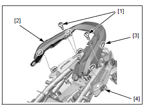
Remove the body cover.
Remove the two socket bolts [1].
Remove the rear cowl [2] by releasing the tabs [3] from the slots [4] of the rear fender B.
Installation is in the reverse order of removal.
DISASSEMBLY/ASSEMBLY
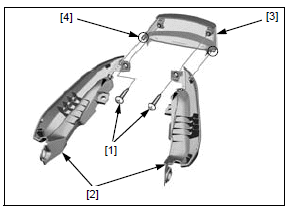
Remove the two tapping screws [1].
Remove the rear side cowls [2] from the rear center cowl [3] by releasing the tabs [4].
Assembly is in the reverse order of disassembly.
REAR FENDER A
REMOVAL/INSTALLATION
EXCEPT U MODEL
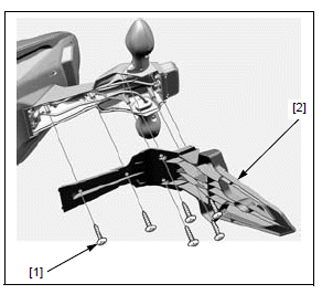
Remove the following:
- Tapping screws [1]
- Rear fender A [2]
Installation is in the reverse order of removal.
U MODEL
Remove four tapping screws [1] and rear fender cover [2].
Remove two tapping screws [3] and rear fender A [4].
Installation is in the reverse order of removal.
REAR FENDER STAY
REMOVAL/INSTALLATION
Remove the seat.
Disconnect the following connectors [1]:
- Rear turn signal light 2P (left: Orange, right: Light blue)
- License light 2P (White)
Remove the three socket bolts [2] and rear fender stay [3] by pulling the wires out from the holes [4] of the rear fender B.
Installation is in the reverse order of removal.
TORQUE:
Rear fender stay mounting bolt:
12 N*m (1.2 kgf*m, 9 lbf*ft)
REAR FENDER B
REMOVAL/INSTALLATION
Remove the following:
- Fuel tank
- Battery
- Rear fender stay
- Rear cowl
- Brake/tail light unit
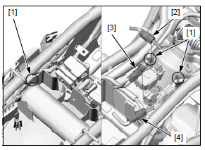
Release the following:
- Three wire clips [1]
- Fuel pump 3P (Black) connector [2]
- Rear brake light switch 2P (Black) connector [3]
- Rear wheel speed sensor 2P (Gray) connector [4] (CBR650FA, CB650FA only)
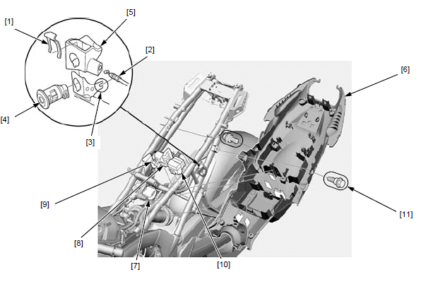
Remove the spring [1].
Release the seat lock cable [2] from the cable guide [3], then disconnect it from the key cylinder [4].
Remove the key cylinder cover [5] and key cylinder.
Release the following from the rear fender B [6]:
- Junction box cover [7]
- Starter relay switch [8]
- DLC [9]
- Fuse boxes [10]
Remove the two bolts [11].
Slide the rear fender B downward and remove it out of the frame.
Installation is in the reverse order of removal.
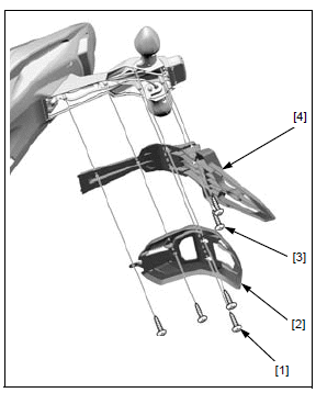
DRIVE SPROCKET COVER
REMOVAL/INSTALLATION
Remove the following:
- Pinch bolt [1]
- Gearshift arm [2]
- Two socket bolts [3]
- Drive sprocket cover [4]
Remove the chain guide [5] by releasing the two wire clips [6].
Installation is in the reverse order of removal.
NOTE:
- Route the wires and hoses into the guide of the sprocket cover.
- Align the slit in the gearshift arm with the punch mark on the spindle.
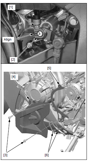
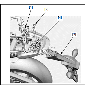
DRIVE CHAIN COVER/MUD GUARD
REMOVAL/INSTALLATION
Remove the following:
- Three socket bolts [1]
- Bolt [2] and hose clamp [3]
- Drive chain cover/mud guard [4]
Installation is in the reverse order of removal.
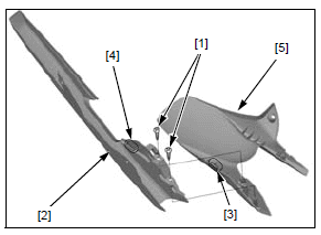
DISASSEMBLY/ASSEMBLY
Remove the two tapping screws [1].
Remove the drive chain cover [2] by releasing the tab [3] from the groove [4] of the mud guard [5].
Assembly is in the reverse order of disassembly.
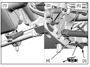
SIDESTAND
REMOVAL/INSTALLATION
Remove the sidestand switch from the sidestand pivot.
Retract the sidestand and remove the following:
- Springs [1]
- Pivot nut [2] and bolt [3]
- Washer [4]
- Sidestand [5]
Apply molybdenum disulfide grease to the sidestand pivot bolt sliding surface.
Install the sidestand, washer and sidestand pivot bolt.
Tighten the sidestand pivot bolt to the specified torque.
TORQUE: 10 N*m (1.0 kgf*m, 7 lbf*ft)
Loosen the sidestand pivot bolt 45 - 90º.
Install and tighten the sidestand pivot nut to the specified torque while holding the pivot bolt.
TORQUE: 30 N*m (3.1 kgf*m, 22 lbf*ft)
Install the sidestand springs.
Install the sidestand switch.
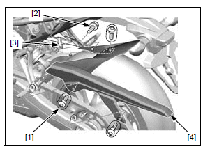
FOOTPEG BRACKET
REMOVAL/INSTALLATION
NOTE:
- For right rider footpeg bracket removal/installation, refer to following:
- Brake pedal
- Rear master cylinder
LEFT RIDER FOOTPEG BRACKET
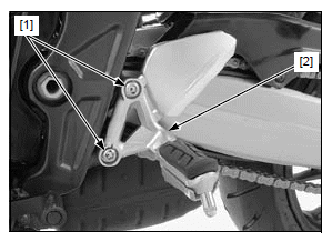
Remove the two bolts [1] and footpeg bracket [2].
Installation is in the reverse order of removal.
TORQUE:
Rider footpeg bracket bolt:
37 N*m (3.8 kgf*m, 27 lbf*ft)
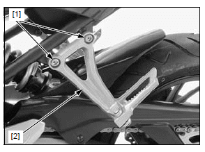
PASSENGER FOOTPEG BRACKET
Remove the two bolts [1] and footpeg bracket [2].
Installation is in the reverse order of removal.
TORQUE:
Passenger footpeg bracket bolt:
27 N*m (2.8 kgf*m, 20 lbf*ft)
EXHAUST PIPE/MUFFLER
REMOVAL/INSTALLATION
Remove the drive sprocket cover.
Pull down the radiator.
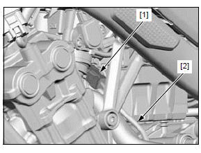
Disconnect the O2 sensor 4P (Black) connector [1] and remove the O2 sensor wire [2] out of the frame.
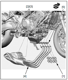
Remove the following:
- Joint nuts [1]
- Mounting bolts [2] and collars [3]
- Exhaust pipe/muffler [4]
- Gaskets [5]
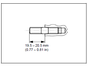
Be sure to verify the length from the stud bolt head to the cylinder head surface.
Install new gaskets.
Install the exhaust pipe/muffler with the collars, mounting bolts and joint nuts by setting the exhaust pipe flanges onto the stud bolts, and screw all the fasteners in fully.
Tighten the joint nuts first to the specified torque, then tighten the mounting bolts.
TORQUE:
Exhaust pipe joint nut: 18 N*m (1.8 kgf*m, 13 lbf*ft)
Muffler mounting bolt: 22 N*m (2.2 kgf*m, 16 lbf*ft)
Install the removed parts in the reverse order of removal.
STUD BOLT REPLACEMENT
Remove the exhaust pipe/muffler.
Thread two nuts onto the stud bolt and tighten them together, and use a wrench on them to turn the stud bolt out.
Install a new stud bolt with the short threads facing the cylinder head.
Tighten the stud bolt securely.
After installation, check that the length from the bolt head to the cylinder head surface is within specification.
Install the exhaust pipe/muffler.
See also:
 Honda CBR650 - Service manual > Body panel locations/removal chart
CBR650F/FA Front fender Windscreen Rearview mirror Headlight assembly Upper cowl A Upper cowl B Meter panel Middle cowl Under cowl Seat Body cover Rear cowl Rear fender cover (U model only) Rear fender A Rear fender stay Rear fender B Drive sprocket cover Drive chain cover/mud guard This chart shows removal order of frame covers by means of arrow.
 Rider's Manual BMW R 1250 GS GSA
 Owner's Manual Harley-Davidson Sportster XL1200X Forty-Eight
 Owner's Manual Honda CBR650R
 Service manual Honda CBR650
 Owner's Manual Honda PCX125
 Owner's Manual Kawasaki Z1000SX
 Service manual Kawasaki Z1000SX
 Owner's Manual Lexmoto Echo
 Owner's Manual Royal Enfield Interceptor 650
 Service manual Royal Enfield Interceptor 650
 Owner's Manual Yamaha MT-07