 Honda CBR650 - Service manual > Body panel locations/removal chart
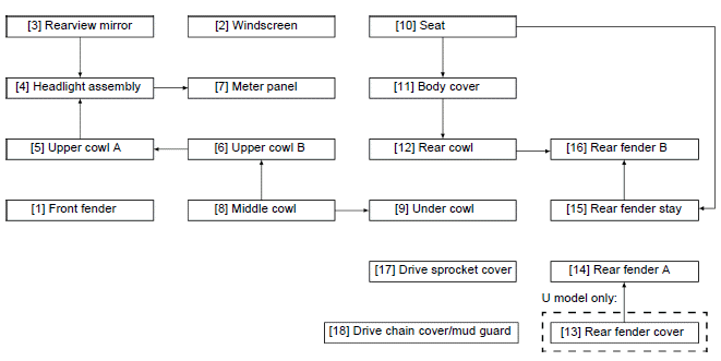
CBR650F/FA
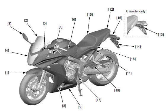
- Front fender
- Windscreen
- Rearview mirror
- Headlight assembly
- Upper cowl A
- Upper cowl B
- Meter panel
- Middle cowl
- Under cowl
- Seat
- Body cover
- Rear cowl
- Rear fender cover (U model only)
- Rear fender A
- Rear fender stay
- Rear fender B
- Drive sprocket cover
- Drive chain cover/mud guard
- This chart shows removal order of frame covers by means of arrow.
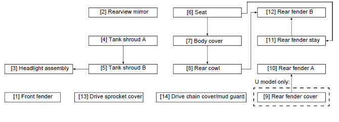
CB650F/FA
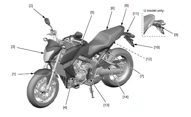
- Front fender
- Rearview mirror
- Headlight assembly
- Tank shroud A
- Tank shroud B
- Seat
- Body cover
- Rear cowl
- Rear fender cover (U model only)
- Rear fender A
- Rear fender stay
- Rear fender B
- Drive sprocket cover
- Drive chain cover/mud guard
- This chart shows removal order of frame covers by means of arrow.
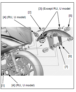
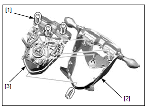
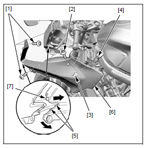
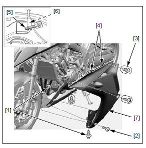
FRONT FENDER
REMOVAL/INSTALLATION
Remove the following:
- Brake hose clamp bolts [1]
- Brake pipe joint mounting bolt [2]
- Two collars [3] (Except RU, U model)
- Two reflex reflectors [4] (RU, U model)
- Four socket bolts [5]
- Front fender [6]
- Four collars [7]
Installation is in the reverse order of removal.
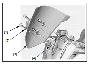
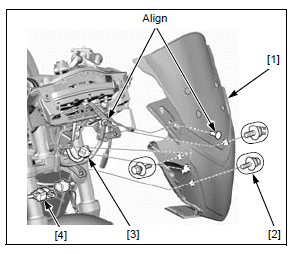
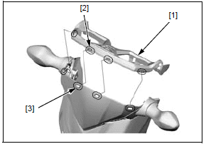
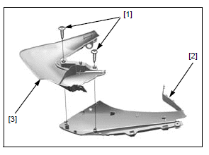
WINDSCREEN (CBR650F/FA)
REMOVAL/INSTALLATION
- Remove the following:
- Four socket bolts [1]
- Four plastic washers [2]
- Windscreen [3]
- Four well nuts [4]
Installation is in the reverse order of removal.
TORQUE:
Windscreen socket bolt:
1.5 N*m (0.2 kgf*m, 1.1 lbf*ft)
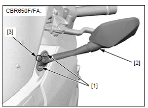
REARVIEW MIRROR
REMOVAL/INSTALLATION
CBR650F/FA
Remove the two socket bolts [1] and rearview mirror [2].
Installation is in the reverse order of removal.
NOTE:
- Install with the reference mark [3] facing the rear side.
TORQUE:
Rearview mirror mounting socket bolt:
10 N*m (1.0 kgf*m, 7 lbf*ft)
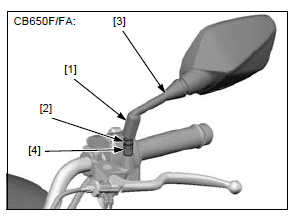
CB650F/FA
Slide the boot [1] off from the lock nut [2].
Loosen the lock nut (left-hand threads) and remove the rearview mirror [3].
Remove the mirror adaptor [4].
Installation is in the reverse order of removal.
TORQUE:
Rearview mirror lock nut:
20 N*m (2.0 kgf*m, 15 lbf*ft)
Rearview mirror adaptor:
20 N*m (2.0 kgf*m, 15 lbf*ft)
HEADLIGHT ASSEMBLY
HEADLIGHT ASSEMBLY REMOVAL/ INSTALLATION
CBR650F/FA
Remove the following:
- Rearview mirror
- Upper cowls A
Support the headlight assembly [1] securely and remove the three washer bolts [2].
Disconnect the headlight 3P (Black) connector [3].
Release the front position light 4P (Black) connector [4] from the stay and disconnect it Installation is in the reverse order of removal.
- Align the headlight boss with the hole of the stay.
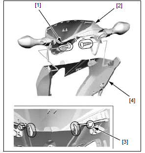
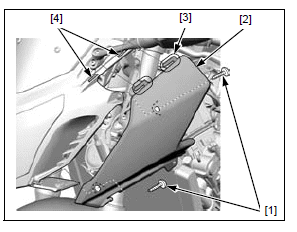
CB650F/FA
Remove the tank shroud B.
Release the following connectors from the stay and disconnect them:
- Front sub harness 12P (Black) [1]
- Front sub harness 6P (Black) [2]
- Front sub harness 4P (Black) [3]
- Front sub harness 2P (Brown) [4]
Release the wire clip [5].
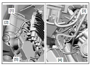
Remove the headlight assembly from the bottom bridge.
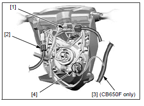
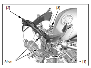
Disconnect the immobilizer receiver 4P (Black) connector [1] and release it from the headlight stay.
Disconnect the Ignition switch 2P (Brown) connector [2].
CB650F only:
Release the front brake hose [3] from the guide [4] of the headlight stay.
Installation is in the reverse order of removal.
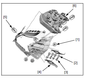
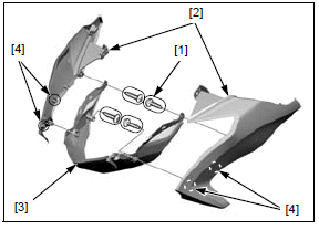
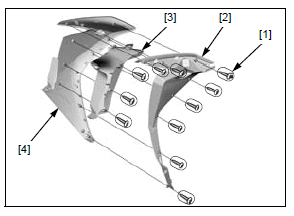
DISASSEMBLY/ASSEMBLY
CBR650F/FA
Remove the following.
- Four nuts [1]
- Four collars [2]
- Four socket bolts [3]
- Windscreen stays [4]
- Four tapping screws [5]
- Headlight unit [6]
Assembly is in the reverse order of disassembly.
CB650F/FA
Remove the four tapping screws [1] and headlight cover assembly [2] from the headlight stay assembly [3].
Remove the meter panel [1] by releasing the slots [2] from the tabs [3] of the meter visor.
Remove the two tapping screws [1].
Remove the meter visor assembly [2] by releasing the hooks [3] from the headlight cover [4].
Remove the four tapping screws [1].
Remove the headlight cover A [2] from the headlight cover B [3] by releasing the hooks [4].
Assembly is in the reverse order of disassembly.
UPPER COWL B (CBR650F/FA)
REMOVAL/INSTALLATION
Remove the middle cowl.
Remove the two socket bolt A [1], socket bolt B [2] and release the boss [3] from the grommet [4] of the fuel tank.
Release the front side tabs [5] from the slot of the upper cowl A.
Pull the upper cowl B [6] rearward and release the tab [7], then remove the upper cowl B.
Installation is in the reverse order of removal.
TORQUE:
Upper cowl socket bolt A:
1.5 N*m (0.2 kgf*m, 1.1 lbf*ft)
DISASSEMBLY/ASSEMBLY
Remove the following:
- Two tapping screws [1]
- Upper cowl B [2]
- Upper cowl C [3]
Assembly is in the reverse order of disassembly.
UPPER COWL A (CBR650F/FA)
REMOVAL/INSTALLATION
- Remove the upper cowl B
- Remove the two tapping screws [1]
- Remove the upper cowl A [2] by releasing the hooks [3] from the slots [4] of the headlight
- Installation is in the reverse order of removal.
METER PANEL (CBR650F/FA)
REMOVAL/INSTALLATION
Remove the headlight assembly.
Release the wire clip [1].
Remove the meter panel [2] from the four bosses [3].
Installation is in the reverse order of removal.
- Align the boss with the hole of the headlight stay.
MIDDLE COWL (CBR650F/FA)
REMOVAL/INSTALLATION
Remove the following:
- Two trim clips (pin head) [1]
- Socket bolt A [2]
- Three socket bolts B [3]
Release the snap fit clips [4].
Open the wire clamp [5] and disconnect the front turn signal light 3P connector [6], then remove the middle cowl [7].
Installation is in the reverse order of removal.
TORQUE:
Middle cowl socket bolt A:
1.5 N*m (0.2 kgf*m, 1.1 lbf*ft)
DISASSEMBLY/ASSEMBLY
Remove the following:
- Tapping screws [1]
- Inner panel [2]
- Middle cowl B [3]
- Middle cowl A [4]
Assembly is in the reverse order of disassembly.
TANK SHROUD A (CB650F/FA)
REMOVAL/INSTALLATION
Remove the four socket bolts [1].
Release the snap fit clips [2] and remove the tank shroud A [3].
Installation is in the reverse order of removal.
DISASSEMBLY/ASSEMBLY
Remove the following:
- Four tapping screws [1]
- Tank shroud A [2]
- Inner panel [3]
Assembly is in the reverse order of disassembly.
TANK SHROUD B (CB650F/FA)
REMOVAL/INSTALLATION
Remove the tank shroud A.
Remove the three socket bolts [1] and tank shroud B [2].
Installation is in the reverse order of removal.
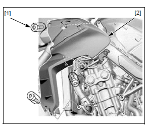
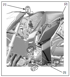
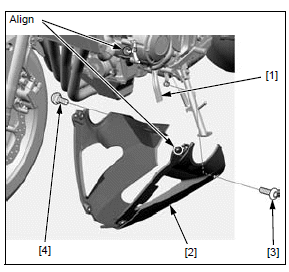
UNDER COWL (CBR650F/FA)
REMOVAL/INSTALLATION
Remove the middle cowls.
Release the hoses [1] from the under cowl [2].
Remove the following:
- Socket bolt A [3] (left side)
- Socket bolt B [4] (right side)
- Under cowl
Installation is in the reverse order of removal.
- Align the slots with the hook of the stay.
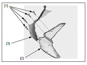
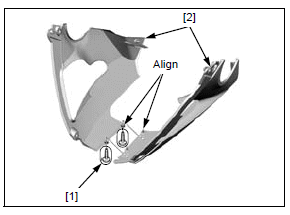
DISASSEMBLY/ASSEMBLY
Remove the two tapping screws [1] and separate the under cowls [2].
Assembly is in the reverse order of disassembly.
- Align the holes with the bosses.
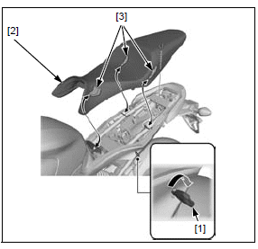
SEAT
REMOVAL/INSTALLATION
Unhook the seat with the ignition key [1].
Remove the seat [2] by pulling it rearward.
Install the seat by inserting the prongs [3] under the frame.
Push down the rear of the seat securely to lock it.
See also:
 Honda CBR650 - Service manual > Frame/body panels/exhaust system
SERVICE INFORMATION GENERAL This section covers removal and installation of the body panels and exhaust system. When disassembling, mark and store the mounting fasteners to ensure that they are reinstalled in their original locations. When installing the covers, make sure the mating areas are aligned properly before tightening the fasteners. Always replace the gaskets with new ones after removing the exhaust system. When installing the exhaust system, loosely install all of the fasteners. Always tighten the exhaust pipe joint nuts first, then tighten the mounting bolt. Always inspect the exhaust system for leaks after installation.
Honda CBR650 - Service manual > Body cover
REMOVAL/INSTALLATION Remove the seat. Remove the following: Special bolt [1] Washer [2] Collar [3] Trim clip (pin head) [4] Trim clip (screw head) [5]
 Rider's Manual BMW R 1250 GS GSA
 Owner's Manual Harley-Davidson Sportster XL1200X Forty-Eight
 Owner's Manual Honda CBR650R
 Service manual Honda CBR650
 Owner's Manual Honda PCX125
 Owner's Manual Kawasaki Z1000SX
 Service manual Kawasaki Z1000SX
 Owner's Manual Lexmoto Echo
 Owner's Manual Royal Enfield Interceptor 650
 Service manual Royal Enfield Interceptor 650
 Owner's Manual Yamaha MT-07