 Kawasaki Z1000SX - Service manual > Brakes
Brake Fluid Leak (Brake Hose and Pipe) Inspection
- For ABS equipped models, remove the fuel tank (see Fuel Tank Removal in the Fuel System (DFI) chapter).
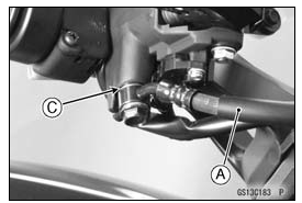
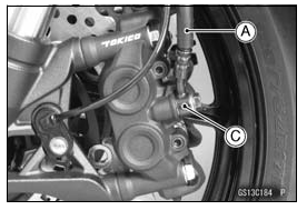
- Apply the brake lever or pedal and inspect the brake fluid leak from the
brake hoses [A], pipes (ABS equipped models) [B] and fittings [C].
If the brake fluid leaked from any position, inspect or replace the problem part.
Brake Hose and Pipe Damage and Installation Condition Inspection
- For ABS equipped models, remove the fuel tank (see Fuel Tank Removal in the Fuel System (DFI) chapter).
- Inspect the brake hoses and fittings for deterioration, cracks and signs
of leakage.
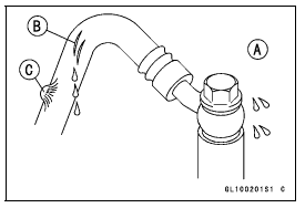
- The high pressure inside the brake line can cause fluid to leak [A] or the hose, pipe (ABS equipped models) to burst if the line is not properly maintained. Bend and twist the rubber hose while examining it.
Replace the hose and pipe (ABS equipped models) if any crack [B], bulge [C] or leakage is noticed.
Tighten any brake hose banjo bolts and brake pipe joint nuts.
Torque -
Brake Hose Banjo Bolts: 25 N*m (2.5 kgf*m, 18 ft*lb)
Brake Pipe Joint Nuts: 18 N*m (1.8 kgf*m, 13 ft*lb) (ABS Equipped Models)
- Inspect the brake hose routing.
If any brake hose routing is incorrect, route the brake hose according to Cable, Wire, and Hose Routing section in the Appendix chapter.
Brake Operation Inspection
- Inspect the operation of the front and rear brake by running the vehicle
on the dry road.
If the brake operation is insufficiency, inspect the brake system.
WARNING When test riding the vehicle, be aware of surrounding traffic for your safety.
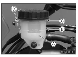
Brake Fluid Level Inspection
- Check that the brake fluid level in the front brake reservoir [A] is above the lower level line [B].
NOTE
- Hold the reservoir horizontal by turning the handlebar when checking brake fluid level.
If the fluid level is lower than the lower level line, fill the reservoir to the upper level line [C].
- Remove the stopper [D].
- Tighten:
Torque - Front Master Cylinder Reservoir Cap Stopper
Screw: 1.2 N*m (0.12 kgf*m, 11 in*lb)
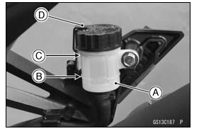
- Check that the brake fluid level in the rear brake reservoir [A] is
above the lower level line [B].
If the fluid level is lower than the lower level line, fill the reservoir to the upper level line [C].
- Remove the stopper [D].
WARNING Mixing brands and types of brake fluid can reduce the brake system's effectiveness and cause an accident resulting in injury or death. Do not mix two brands of brake fluid. Change the brake fluid in the brake line completely if the brake fluid must be refilled but the type and brand of the brake fluid that is already in the reservoir are unidentified.
Recommended Disc Brake Fluid
Grade: DOT4
- Follow procedure below to install the front/rear brake fluid reservoir
cap correctly.
- First, tighten the rear brake fluid reservoir cap [B] clockwise [C] by hand until slight resistance is felt indicating that the cap is seated on the reservoir body, then tighten the cap an additional 1/6 turn [D] while holding the brake fluid reservoir body [A].
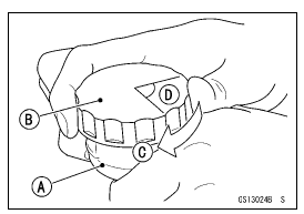
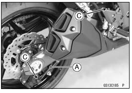
Brake Pad Wear Inspection
- Remove the brake pads (see Front/Rear Brake Pad Removal in the Brakes chapter).
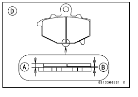
- Check the lining thickness [A] of the pads in each caliper.
If the lining thickness of either pad is less than the service limit [B], replace both pads in the caliper as a set.
[C] Front Brake Pad
[D] Rear Brake Pad
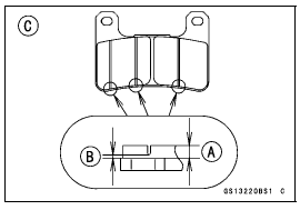
Pad Lining Thickness
Standard:
Front 4.0 mm (0.16 in.)
Rear 5.0 mm (0.20 in.)
Service Limit: 1 mm (0.04 in.)
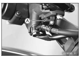
Brake Light Switch Operation Inspection
- Turn on the ignition switch.
- The brake light [A] should go on when the brake lever is applied or after the brake pedal is depressed about 10 mm (0.39 in.).
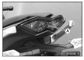
If it does not, adjust the brake light switch as follows.
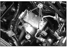
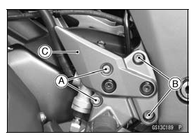
- Remove:
Rear Lower Fairing (see Rear Lower Fairing Removal in the Frame chapter)
Rear Master Cylinder Mounting Bolts [A]
Footpeg Bracket Bolts [B]
Footpeg Bracket [C]
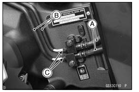
- While holding the switch body, turn the adjusting nut to adjust the
switch.
Switch Body [A]
Adjusting Nut [B]
Light sooner as the body rises [C]
Light later as the body lowers [D]
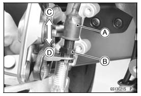
NOTICE To avoid damaging the electrical connections inside the switch, be sure that the switch body does not turn during adjustment.
If it does not go on, inspect or replace the following items.
Battery (see Charging Condition Inspection in the Electrical System chapter)
Brake Light (see Tail/Brake Light Removal in the Electrical System chapter)
Main Fuse 30 A and Taillight Fuse 10 A (see Fuse Inspection in the Electrical System chapter)
Front Brake Light Switch [A] (see Switch Inspection in the Electrical System chapter)
Rear Brake Light Switch (see Switch Inspection in the Electrical System chapter)
Harness (see Wiring Inspection in the Electrical System chapter)
- Tighten:
Torque -
Front Footpeg Bracket Bolt: 25 N*m (2.5 kgf*m, 18 ft*lb)
Rear Master Cylinder Mounting Bolts: 25 N*m (2.5 kgf*m, 18 ft*lb)
See also:
 Kawasaki Z1000SX - Service manual > Final Drive
Drive Chain Lubrication Condition Inspection If a special lubricant is not available, a heavy oil such as SAE 90 is preferred to a lighter oil because it will stay on the chain longer and provide better lubrication. If the chain appears especially dirty, clean it before lubrication.
Kawasaki Z1000SX - Service manual > Suspension
Front Forks/Rear Shock Absorber Operation Inspection Pump the forks down and up [A] 4 or 5 times, and inspect the smooth stroke. If the forks do not smoothly or noise is found, inspect the fork oil level or fork clamps (see Front Fork Oil Change in the Suspension chapter). Pump the seat down and up [A] 4 or 5 times, and inspect the smooth stroke.
 Rider's Manual BMW R 1250 GS GSA
 Owner's Manual Harley-Davidson Sportster XL1200X Forty-Eight
 Owner's Manual Honda CBR650R
 Service manual Honda CBR650
 Owner's Manual Honda PCX125
 Owner's Manual Kawasaki Z1000SX
 Service manual Kawasaki Z1000SX
 Owner's Manual Lexmoto Echo
 Owner's Manual Royal Enfield Interceptor 650
 Service manual Royal Enfield Interceptor 650
 Owner's Manual Yamaha MT-07