 Honda CBR650 - Service manual > Camshaft
REMOVAL
NOTE:
- The camshaft can be serviced with the engine installed in the frame.
Remove the cylinder head cover.
Make sure the No. 1 piston is at TDC (Top Dead Center) on the compression stroke.
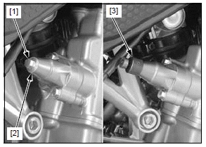
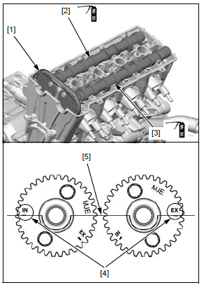
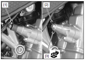
Remove the sealing bolt [1] and sealing washer [2].
Turn the cam chain tensioner lifter shaft fully in (clockwise) and secure it using the special tool.
TOOL:
[3] Tensioner stopper 070MG-0010100
Be careful not to let the cam chain guide bolts fall into the crankcase.
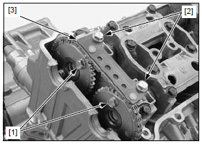
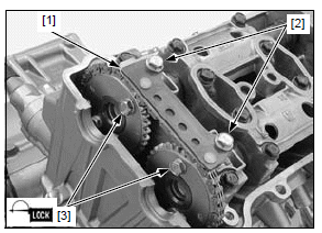
If you replace the camshaft and/or cam sprocket, loosen the cam sprocket bolts [1].
- Turn the crankshaft clockwise one full turn (360º), loosen the other cam sprocket bolts, then reset the No.1 piston to the TDC (Top Dead Center) on the compression stroke.
Remove the bolts [2] and cam chain guide B [3].
NOTICE
- From outside to inside, loosen the bolts in a crisscross pattern in several steps or the camshaft holder might break.
Be careful not to let the camshaft holder bolts fall into the crankcase.
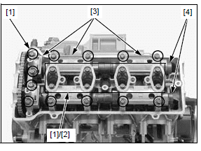
Loosen the camshaft holder bolts [1] gradually in a crisscross pattern in 2 or 3 steps, and remove them and washers [2].
Remove the camshaft holders [3] with the dowel pins from the cylinder head.
- Do not forcibly remove the dowel pins from the camshaft holders.
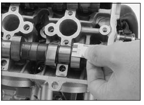
Remove the camshafts [4] by removing the cam chain from the cam sprockets.
- Attach a piece of wire to the cam chain to prevent it from falling into the crankcase.
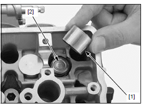
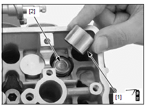
Remove the valve lifters [1] and shims [2].
- Be careful not to damage the valve lifter bore.
- Shim may stick to the inside of the valve lifter. Do not allow the shims to fall into the crankcase.
- Mark all valve lifters and shims to ensure correct reassembly in their original locations.
- The valve lifter can be easily removed with a valve lapping tool or magnet.
- The shims can be easily removed with a tweezers or magnet.
INSPECTION
Inspect the following parts for damage, abnormal wear, deformation, burning or clogs in oil passages.
- Cam sprockets/camshafts
- Camshaft holders/dowel pins
- Cam chain guide B
Measure each part according to CYLINDER HEAD/ VALVES SPECIFICATIONS.
Replace any part if it is out of service limit.
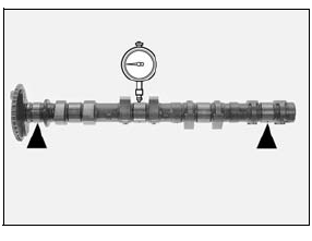
CAMSHAFT RUNOUT
Support both sides of the camshaft (at journals) with V-blocks and check the camshaft runout with a dial gauge.
SERVICE LIMIT: 0.04 mm (0.002 in)
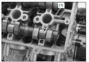
CAMSHAFT OIL CLEARANCE
Wipe any oil from the journals of the camshaft, cylinder head and camshaft holders.
Install the camshafts onto the cylinder head.
Lay a strip of plastigauge [1] lengthwise on top of each camshaft journal avoiding the oil hole.
NOTE:
- Do not rotate the camshaft during inspection.
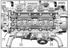
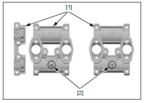
Be sure the dowel pins in the cam shaft holders are aligned with the holes in the cylinder head.
Install each camshaft holder to the correct locations with the identification marks.
- No mark: right camshaft holder [1]
- "R" mark: center camshaft holder [2]
- "L" mark: left camshaft holder [3]
Apply engine oil to the threads and seating surfaces of the camshaft holder bolts [4].
Install the holder bolts and sealing washers [5].
Finger tighten the bolts.
Gradually tighten the camshaft holder bolts until the camshaft holders lightly contact the cylinder head surface.
NOTICE
Failure to tighten the camshaft holder in a criss-cross pattern might cause a camshaft holder to break.
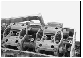
Tighten all camshaft holder bolts in the numerical order cast on the camshaft holders.
TORQUE:12 N*m (1.2 kgf*m, 9 lbf*ft)
Remove the camshaft holders and measure the width of each plastigauge.
The widest thickness determines the oil clearance.
SERVICE LIMIT: 0.10 mm (0.004 in)
When the service limits are exceeded, replace the camshaft and recheck the oil clearance.
Replace the cylinder head and camshaft holders as a set if the clearance still exceeds the service limit.
INSTALLATION
Apply molybdenum oil solution to the outer surface of each valve lifter [1].
Install the shims and valve lifters in their original locations.
Install the shims [2] on the retainers and valve lifters into the valve lifter bores.
Each camshaft has an identification mark.
- "IN" mark [1]: Intake camshaft
- "EX" mark [2]: Exhaust camshaft
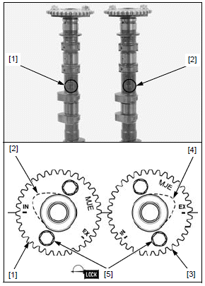
If the cam sprockets are removed, install the cam sprockets onto the camshafts.
- Install the intake cam sprocket [1] with the timing mark (IN) facing outward and the No.1 cam lobes [2] facing up and out as shown.
- Install the exhaust cam sprocket [3] with the timing mark (EX) facing outward and the No.1 cam lobes [4] facing up and out as shown.
Clean and apply a locking agent to the cam sprocket bolt threads.
Install the cam sprocket bolts [5].
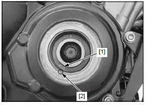
Rotate the crankshaft clockwise slowly and align the "T" mark [1] with the index notch [2] in the crankcase cover.
Apply molybdenum oil solution to the camshaft journals, lobes and thrust surfaces.
Install the cam chain [1] over the cam sprockets of the intake [2] and exhaust [3] camshafts, making sure that the timing marks [4] on the cam sprockets are flush with the top surface [5] of the cylinder head.
- Install each camshaft to the correct locations with the identification
marks.
"IN" mark: Intake camshaft "EX" mark: Exhaust camshaft
Coat new O-rings with oil and install them into the grooves in the camshaft holders.
Apply molybdenum oil solution to the camshaft journals of the camshaft holders.
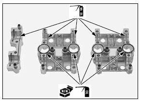
Install each camshaft holder [1] to the correct locations with the identification marks [2].
- No mark: right camshaft holder
- "R" mark: center camshaft holder
- "L" mark: left camshaft holder
Apply engine oil to the camshaft holder bolt [1] threads and seating surface.
Install the camshaft holder bolts with new sealing washers [2].
NOTICE
Failure to tighten the camshaft holder in a crisscross pattern may cause the camshaft holder to break.
From inside to outside tighten the camshaft holder bolts gradually until the camshaft holders seats on the cylinder head.
Tighten the camshaft holder bolts in a crisscross pattern in 2 or 3 steps to the specified torque.
TORQUE:12 N*m (1.2 kgf*m, 9 lbf*ft)
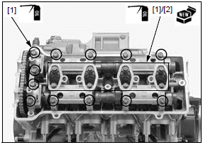
Install the cam chain guide B [1].
Be careful not to let the cam chain guide bolts fall into the crankcase.
Install and tighten the cam chain guide bolts [2] securely.
If the cam sprocket was removed from the camshaft, apply a locking agent to the cam sprocket bolt [3] threads.
Tighten the cam sprocket bolts to the specified torque.
TORQUE:20 N*m (2.0 kgf*m, 15 lbf*ft)
Turn the crankshaft clockwise one full turn (360º) and tighten the other cam sprocket bolts.
Remove the tensioner stopper [1] from the cam chain tensioner lifter.
Turn the crankshaft clockwise several times, and align the "T" mark on the primary drive gear with the index notch on the right crankcase cover.
Recheck the valve timing.
Inspect the valve clearance.
Install the sealing bolt [2] with a new sealing washer [3] and tighten it securely.
Install the cylinder head cover.
See also:
 Honda CBR650 - Service manual > Service information
GENERAL This section covers service of the cylinder head, valves and camshafts. All the services covered in this section can be done with the engine installed in the frame. When disassembling, mark and store the disassembled parts to ensure that they are reinstalled in their original locations. Clean all disassembled parts with cleaning solvent and dry them by blowing them off with compressed air before inspection. Camshafts lubricating oil is fed through oil passages in the cylinder head and camshaft holder. Clean the oil passages before assembling them. Be careful not to damage the mating surfaces when removing the cylinder head cover and cylinder head.
Honda CBR650 - Service manual > Cylinder head
REMOVAL Remove the following: Exhaust pipe/muffler Throttle body Camshaft Disconnect the ECT sensor 2P (Blue) connector [1] and bleeding hose [2].
 Rider's Manual BMW R 1250 GS GSA
 Owner's Manual Harley-Davidson Sportster XL1200X Forty-Eight
 Owner's Manual Honda CBR650R
 Service manual Honda CBR650
 Owner's Manual Honda PCX125
 Owner's Manual Kawasaki Z1000SX
 Service manual Kawasaki Z1000SX
 Owner's Manual Lexmoto Echo
 Owner's Manual Royal Enfield Interceptor 650
 Service manual Royal Enfield Interceptor 650
 Owner's Manual Yamaha MT-07