 Honda CBR650 - Service manual > Cylinder head
REMOVAL
Remove the following:
- Exhaust pipe/muffler
- Throttle body
- Camshaft
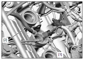
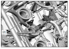
Disconnect the ECT sensor 2P (Blue) connector [1] and bleeding hose [2].
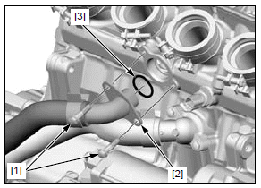
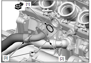
Remove the bolts [1] and water hose joint A [2] from the cylinder head.
Remove the O-ring [3] from the water hose joint A.
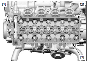
Remove the 6 mm bolts [1].
Loosen the 9 mm washer-bolts [2] in a crisscross pattern in 2 or 3 steps, then remove them.
Remove the cylinder head [3].
NOTE:
- Attach a piece of wire to the cam chain to prevent it from falling into the crankcase.
- Do not tap the cylinder head too hard and do not damage the mating surface with a screwdriver.
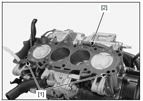
Remove the dowel pins [1] and gasket [2].
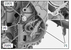
Remove the starter clutch.
Remove the cam chain guide A [1].
Remove the washer bolt [2], collar [3] and cam chain tensioner [4].
Remove the cam chain [5] and timing sprocket [6] from the crankshaft.
DISASSEMBLY
Remove the following:
- Insulator
- ECT sensor
- Spark plugs
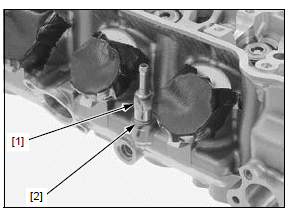
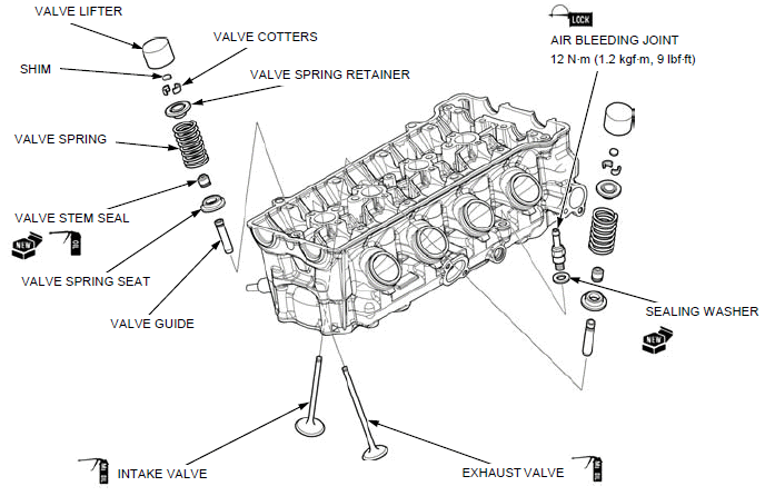
Remove the air bleeding joint [1] and sealing washer [2] from the cylinder head.
Remove the spark plugs from the cylinder head.
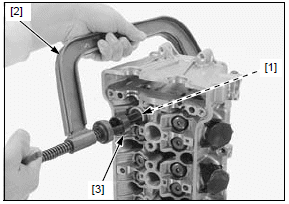
Install the tappet hole protector [1] into the valve lifter bore.
TOOL:
[1] Tappet hole protector 07HMG-MR70002
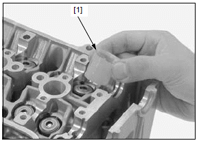
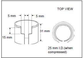
An equivalent tool can easily be made from a plastic 35 mm film container as shown.
To prevent loss of tension, do not compress the valve springs more than necessary to remove the cotters.
Remove the valve spring cotters [1] using the special tools as shown.
TOOLS:
[2] Valve spring compressor 07757-0010000
[3] Valve spring compressor attachment 07959-KM30101
Mark all parts during disassembly so they can be placed back in their original locations.
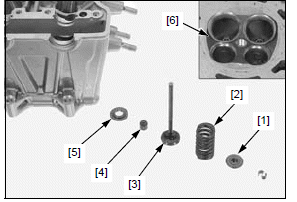
Remove the valve spring compressor and remove the following:
- Valve spring retainers [1]
- Valve springs [2]
- Valves [3]
- Valve stem seals [4]
- Valve spring seats [5]
Avoid damaging the cylinder mating surface and valve seat surfaces.
Remove the carbon deposits from the combustion chamber [6] and clean off the cylinder head gasket surface.
INSPECTION
Inspect the following parts for damage, abnormal wear, deformation, burning or clogs in oil passages.
- Cylinder head
- Valve springs
- Valves
- Valve guides
- Cam chain
- Cam chain timing sprocket
- Cam chain guide A
- Cam chain tensioner
Measure each part and clearance according to CYLINDER HEAD/VALVES SPECIFICATIONS.
Replace any part if it is out of service limit.
- Ream the valve guide using the valve guide reamer to remove any carbon build up before measuring the guide.
- Refer to valve seat inspection.
VALVE GUIDE REPLACEMENT
Disassemble the cylinder head.
Chill new valve guides in a freezer for about 1 hour.
NOTE:
- Be sure to wear heavy gloves to avoid burns when handling the heated cylinder head.
- Using a torch to heat the cylinder head may cause warpage.
Heat the cylinder head to 130 - 140ºC (266 - 284ºF) with a hot plate or oven. Do not heat the cylinder head beyond 150ºC (302ºF). Use temperature indicator sticks, available from welding supply stores, to be sure the cylinder head is heated to the proper temperature.
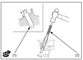
Support the cylinder head and drive the valve guides [1] out of the cylinder head from the combustion chamber side.
TOOL:
[2] Valve guide driver, 4.5 mm 07HMD-ML00101
Take out new valve guides [1] from the freezer.
While the cylinder head is still heated, drive new valve guides from the camshaft side until the exposed height is specified value.
TOOL:
[2] Valve guide adjusting driver 07743-0020000
SPECIFIED HEIGHT:
IN/EX: 12.70 - 13.00 mm (0.500 - 0.512 in)
Let the cylinder head cool to room temperature.
Ream new valve guides after installation.
NOTE:
- Take care not to tilt or lean the reamer [1] in the guide while reaming.
- Use cutting oil on the reamer during this operation.
Insert the reamer from the combustion chamber side of the cylinder head and always rotate the reamer clockwise.
TOOL:
Valve guide reamer, 4.5 mm 07HMH-ML00101
Clean the cylinder head thoroughly to remove any metal particles after reaming and reface the valve seat.
VALVE SEAT INSPECTION/REFACING INSPECTION
Disassemble the cylinder head.
Clean the intake and exhaust valves thoroughly to remove carbon deposits.
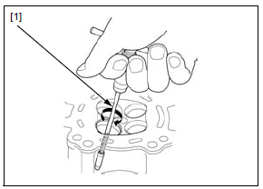
Apply a light coat of Prussian Blue to the valve seats.
Tap the valve against the valve seat several times using a hand-lapping tool [1], without rotating the valve to make a clear pattern.
The valves cannot be ground. If the valve face is burned, badly worn or if it contacts the seat unevenly, replace the valve.
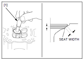
Remove the valve and inspect the valve seat face.
The valve seat contact should be within the specified width and even all around the circumference.
STANDARD: 0.90 - 1.10 mm (0.035 - 0.043 in)
SERVICE LIMIT: 1.5 mm (0.06 in)
If the valve seat width is not within specification, reface the valve seat.
Inspect the valve seat face for:
- Damaged face:
- Replace the valve and reface the valve seat
- Uneven seat width:
- Bent or collapsed valve stem; Replace the valve and reface the valve seat
- Contact area (too low or too high):
- Reface the valve seat
REFACING
Reface the valve seat using the following tools.
TOOLS:
Cutter holder, 4.5 mm 07781-0010600
Seat cutter, 27.5 mm (IN, 45º) 07780-0010200
Seat cutter, 24 mm (EX, 45º) 07780-0010600
Flat cutter, 28 mm (IN, 32º) 07780-0012100
Flat cutter, 24 mm (EX, 32º) 07780-0012500
Interior cutter, 26 mm (IN, 60º) 07780-0014500
Interior cutter, 22 mm (EX, 60º) 07780-0014202
VALVE SEAT WIDTH:
0.90 - 1.10 mm (0.035 - 0.043 in)
NOTE:
- Follow the refacer manufacturer's operating instructions.
- Be careful not to grind the seat more than necessary.
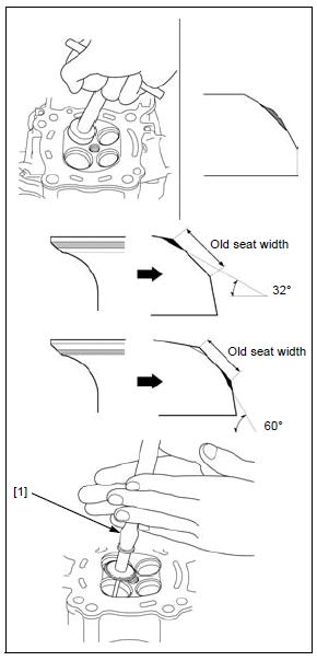
1. Use a 45º seat cutter, remove any roughness or irregularities from the seat.
2. Use a 32º flat cutter, remove the top 1/4 of the existing valve seat material.
3. Use a 60º interior cutter, remove the bottom 1/4 of the existing valve seat material.
4. Using a 45º seat cutter, cut the seat to the proper width.
Make sure that all pitting and irregularities are removed.
5. After cutting the seat, apply lapping compound to the valve face, and lap the valve using light pressure.
NOTE:
- Excessive lapping pressure may deform or damage the seat.
- Change the angle of lapping tool [1] frequently to prevent uneven seat wear.
- Do not allow lapping compound to enter the guides.
After lapping, wash any residual compound off the cylinder head and valve and recheck the seat contact.
Assemble the cylinder head.
ASSEMBLY
Clean the cylinder head assembly with solvent and blow through all oil passages with compressed air.
Apply engine oil to the fitting area of new valve stem seals [1].
Install the valve spring seats [2] and valve stem seals.
Apply molybdenum oil solution to each valve stem end and sliding surface.
Insert the valves [3] into the valve guides while turning them slowly to avoid damage to the valve stem seals.
Install the valve spring [4] with the tightly wound coils facing the combustion chamber.
Install the valve spring retainers [5].
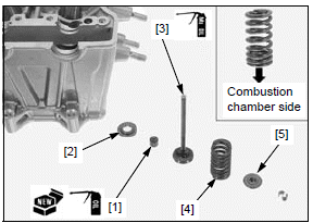
Grease the cotters to ease installation.
To prevent loss of tension, do not compress the valve spring more than necessary.
Install the valve cotters [1] using the special tool.
TOOLS:
[2] Tappet hole protector 07HMG-MR70002
[3] Valve spring compressor 07757-0010000
[4] Valve spring compressor attachment 07959-KM30101
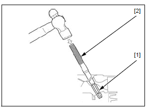
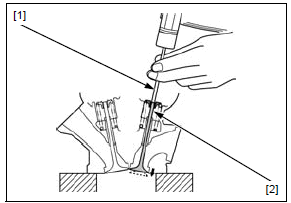
Support the cylinder head above the work bench surface to prevent valve damage.
Place a suitable tool [1] onto the valve stem [2].
Tap the tool gently to seat the valve cotters firmly using a hammer.
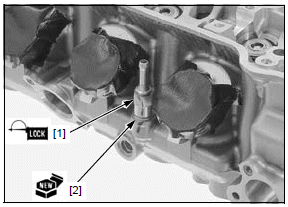
Apply a locking agent to the bleeding joint [1] threads.
Install the bleeding joint with a new sealing washer [2] to the cylinder head.
Tighten the bleeding joint to the specified torque.
TORQUE:12 N*m (1.2 kgf*m, 9 lbf*ft)
Install the following:
- Insulator
- ECT sensor
- Spark plugs
INSTALLATION
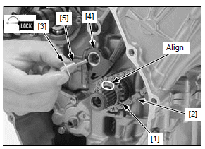
Install the timing sprocket [1] by aligning the wide teeth between the crankshaft and sprocket.
Install the cam chain [2].
Apply locking agent to the cam chain tensioner pivot bolt [3] threads.
Install the cam chain tensioner [4], collar [5] and pivot bolt.
Tighten the cam chain tensioner pivot bolt to the specified torque.
TORQUE:10 N*m (1.0 kgf*m, 7 lbf*ft)
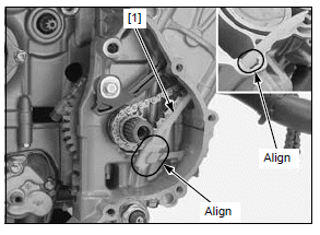
Install the cam chain guide A [1] while aligning its pins with the grooves in the cylinder and its end with the groove in the crankcase.
Install the starter clutch.
Install the dowel pins [1] and a new gasket [2].
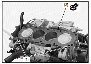
Route the cam chain through the cylinder head and install the cylinder head [1] onto the cylinder.
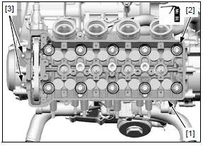
Clean the cylinder head 9 mm washer-bolts [2] in solvent, and dry them thoroughly.
Apply molybdenum oil to the 9 mm washer-bolt threads and seating surfaces.
Install and tighten the 9 mm washer-bolt in a crisscross pattern in 2 or 3 steps to the specified torque.
TORQUE:47 N*m (4.8 kgf*m, 35 lbf*ft)
Install and tighten the 6 mm bolts [3] securely.
Install a new O-ring [1] to the water hose joint A [2].
- Do not apply engine oil to the O-ring.
Install the water hose joint A into the cylinder head and tighten the bolts [3].
Connect the ECT sensor 2P (Blue) connector [1] and bleeding hose [2].
Install the following:
- Camshaft
- Throttle body
- Exhaust pipe/muffler
Cam chain tensioner lifter
REMOVAL/INSTALLATION
NOTE:
- The cam chain tensioner lifter can be serviced with the engine installed in the frame.
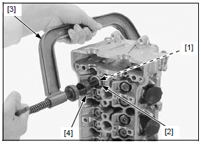
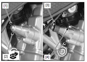
Remove the sealing bolt [1] and sealing washer [2].
Turn the cam chain tensioner lifter shaft fully in (clockwise) and secure it using the special tool.
TOOL:
[3] Tensioner stopper 070MG-0010100
Remove the cam chain tensioner lifter mounting bolts [4].
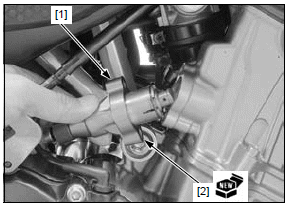
Remove the cam chain tensioner lifter [1] and gasket [2].
Installation is in the reverse order of removal.
NOTE:
- Replace the gasket and sealing washer with new ones.
INSPECTION
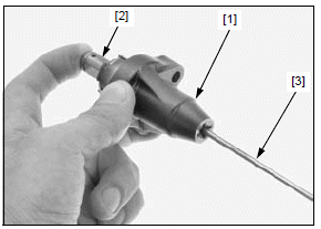
Check the cam chain tensioner lifter [1] operation:
- The cam chain tensioner lifter shaft [2] should not go into the cam chain tensioner lifter body when it is pushed.
- When it is turned clockwise with a tensioner stopper or a screwdriver [3], the cam chain tensioner lifter shaft should be pulled into the cam chain tensioner lifter body. The cam chain tensioner lifter shaft should spring out of the cam chain tensioner lifter body as soon as the stopper tool is released.
See also:
 Honda CBR650 - Service manual > Camshaft
REMOVAL NOTE: The camshaft can be serviced with the engine installed in the frame. Remove the cylinder head cover. Make sure the No. 1 piston is at TDC (Top Dead Center) on the compression stroke.
 Rider's Manual BMW R 1250 GS GSA
 Owner's Manual Harley-Davidson Sportster XL1200X Forty-Eight
 Owner's Manual Honda CBR650R
 Service manual Honda CBR650
 Owner's Manual Honda PCX125
 Owner's Manual Kawasaki Z1000SX
 Service manual Kawasaki Z1000SX
 Owner's Manual Lexmoto Echo
 Owner's Manual Royal Enfield Interceptor 650
 Service manual Royal Enfield Interceptor 650
 Owner's Manual Yamaha MT-07