 Honda CBR650 - Service manual > Combination meter
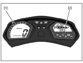
INITIAL OPERATION CHECK
When the ignition switch is turned ON with the engine stop switch " ",
the combination meter will show the entire digital display and the tachometer
segments [1] will increase to full scale, then reduce from full scale to zero.
",
the combination meter will show the entire digital display and the tachometer
segments [1] will increase to full scale, then reduce from full scale to zero.
NOTE:
- If the MIL [2] stays on and it does not go off, refer to MIL circuit troubleshooting.
If the digital display does not function at all, inspect the combination meter power/ground line.
If the power and ground lines are OK, replace the combination meter.
POWER/GROUND LINE INSPECTION
NOTE:
- The DTC 86-1 (serial communication malfunction) will be stored in the ECM if the power or ground line is abnormal. After the service is completed, check the DTC and erase it.
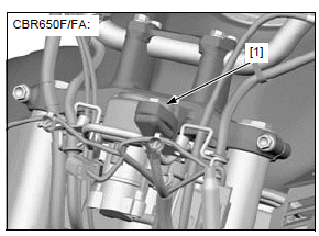
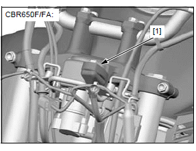
CBR650F/FA:
Remove the combination meter to disconnect the combination meter 16P (Gray) connector [1].
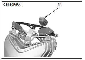
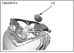
CB650F/FA:
Remove the combination meter to disconnect the combination meter 16P (Gray) connector [1].
Support the headlight stay assembly securely to avoid damaging the wire harness.
Connect the following connector:
- Immobilizer receiver 4P (Black)
- Ignition switch 2P (Brown)
- Front sub harness 12P (Black)
- Front sub harness 4P (Black)
- Front sub harness 2P (Brown)
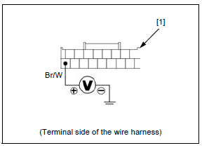
POWER INPUT LINE
Measure the voltage between the combination meter 16P (Gray) connector [1] terminal and ground.
CONNECTION: Brown/white (+) - Ground (-)
There should be battery voltage with the ignition switch turned ON.
If there is no battery voltage, check the following:
- Brown/white wire between the fuse box 1 and combination meter for open circuit
- METER TAIL LICENSE PO fuse (7.5 A)
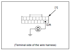
GROUND LINE
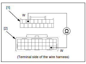
Check for continuity between the combination meter 16P (Gray) connector [1] terminal and ground.
CONNECTION: Green/Red - Ground
There should be continuity at all times.
If there is no continuity, check for open circuit in the Green/red wire.
SERIAL COMMUNICATION LINE INSPECTION
CBR650F/FA:
Disconnect the ECM 33P (Gray) connector.
Remove the combination meter to disconnect the combination meter 16P (Gray) connector [1].
CB650F/FA:
Disconnect the ECM 33P (Gray) connector.
Remove the combination meter to disconnect the combination meter 16P (Gray) connector [1].
Support the headlight stay assembly securely to avoid damaging the wire harness.
Connect the following connectors:
- Immobilizer receiver 4P (Black)
- Ignition switch 2P (Brown)
- Front sub harness 12P (Black)
- Front sub harness 4P (Black)
- Front sub harness 2P (Brown)
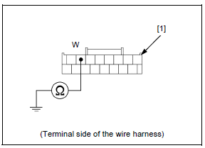
1. Serial Communication Line Short Circuit Inspection
Check for continuity between the wire harness side 16P (Gray) connector [1] terminal and ground.
CONNECTION: White - Ground
Is there continuity?
YES - Short circuit in the White wire between the combination meter and ECM
NO - GO TO STEP 2.
2. Serial Communication Line Open Circuit Inspection
Check for continuity between the wire harness side 16P (Gray) connector [1] and ECM 33P (Gray) connector [2] terminals.
TOOL:
Test probe 07ZAJ-RDJA110
CONNECTION: White - White
Is there continuity?
YES - Loose or poor contact on the related connectors.
NO - Open circuit in the White wire between the combination meter and ECM
REMOVAL/INSTALLATION
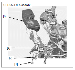
CBR650F/FA:
Remove the meter panel.
Remove the three tapping screws [1], washers [2] and combination meter [3] from the headlight stay.
Disconnect the combination meter 16P (Gray) connector [4].
Installation is in the reverse order of removal
TORQUE:
Combination meter mounting screw:
1.0 N*m (0.1 kgf*m, 0.7 lbf*ft)
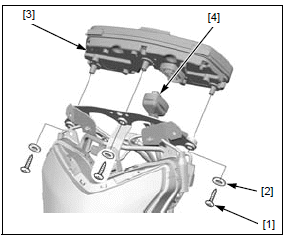
CB650F/FA
Remove the headlight stay assembly.
Remove the three tapping screws [1], washers [2] and combination meter [3] from the headlight stay.
Disconnect the combination meter 16P (Gray) connector [4].
Installation is in the reverse order of removal
TORQUE:
Combination meter mounting screw:
1.0 N*m (0.1 kgf*m, 0.7 lbf*ft)
DISASSEMBLY/ASSEMBLY
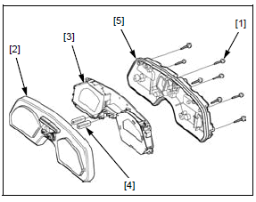
Remove the combination meter assembly.
- CBR650F/FA
- CB650F/FA
Remove the eight tapping screws [1].
Remove the following:
- Upper case (lens) [2]
- Combination meter [3]
- Two extension rods [4]
- Under case [5]
Assembly is in the reverse order of disassembly.
NOTE:
- Be sure the rubber seal is installed in the groove properly.
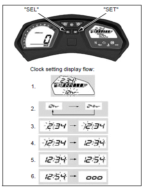
DIGITAL CLOCK SETTING PROCEDURE
Turn the ignition switch ON.
The control is automatically switched from the setting mode to the ordinary display if the button is not pressed for about 30 seconds.
1. Press and hold the SEL and SET buttons until the hour digits starts flashing.
2. Press SEL button to select "12hr" or "24hr". Press SET button. The time format is set, and then the display moves to the clock adjustment.
3. Press the SEL button until the desired hour is displayed (press and hold to advance the hour fast).
4. Press the SET button. The minute digits start flashing.
5. Press the SEL button until the desired minute is displayed (press and hold to advance the minute fast).
6. Press the SET button. The clock is set, and then the display moves to the backlight brightness adjustment ("ooo" - "o" is indicated).
Turn the ignition switch OFF.
Speedometer
SYSTEM INSPECTION
If the speedometer does not operate, check the following:
- Combination meter initial operation
- MIL blinking: If the MIL blinks 11 (DTC 11-1), check the VS sensor system
If the above items are OK, replace the combination meter.
- CBR650F/FA
- CB650F/FA
Tachometer
SYSTEM INSPECTION
If the tachometer does not operate, check the following:
- Combination meter initial operation
- Combination meter indication when the serial communication line is abnormal
- CKP sensor
If the above items are OK, replace the combination meter.
- CBR650F/FA
- CB650F/FA
See also:
 Honda CBR650 - Service manual > Headlight
BULB REMOVAL/INSTALLATION NOTICE Avoid touching the halogen bulb. Finger prints can create hot spots that cause a bulb to break. CBR650F/FA
Honda CBR650 - Service manual > High coolant temperature indicator/ECT sensor, engine oil pressure
indicator/EOP switch
High coolant temperature indicator/ECT sensor SYSTEM INSPECTION NOTE: If the high coolant temperature indicator and digital display do not function at all, refer to combination meter initial operation check.
 Rider's Manual BMW R 1250 GS GSA
 Owner's Manual Harley-Davidson Sportster XL1200X Forty-Eight
 Owner's Manual Honda CBR650R
 Service manual Honda CBR650
 Owner's Manual Honda PCX125
 Owner's Manual Kawasaki Z1000SX
 Service manual Kawasaki Z1000SX
 Owner's Manual Lexmoto Echo
 Owner's Manual Royal Enfield Interceptor 650
 Service manual Royal Enfield Interceptor 650
 Owner's Manual Yamaha MT-07