 Royal Enfield Interceptor 650 - Service manual > Connecting Rods
NOTE
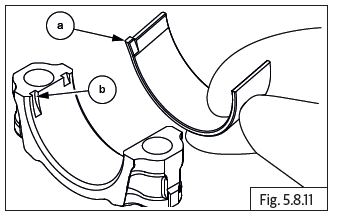
- Ensure new journal bearings are located correctly in the connecting rods and caps.
- Connecting rod bolts are for one time use only. Do not reuse connecting rod bolts. Always replace them.
- Do not interchange connecting rod cap.
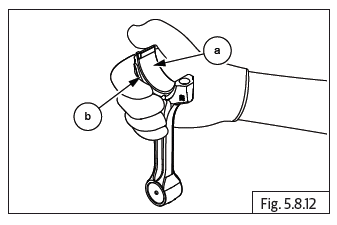
- Ensure the lug (a) in journal bearing is located in the grooves (b) on both connecting rod and cap is seated properly.
WARNING Ensure connecting rods Do not get damaged during assembly.
Ensure crankshaft position is such that connecting rods are not projecting out of spigot.
Support crankcase such that it is atleast 3 cm above surface table.
- Insert connecting rod big end through the cylinder barrel seating area and ensure it is seated properly on the crankshaft.
- Support connecting rod to prevent it from falling off.
- Position connecting rod cap on the crankshaft and ensure the mounting holes of the cap and connecting rod are aligned.
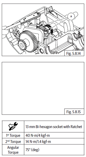
- Lubricate and locate 2 Nos. Bi-hexagon bolts (M9) (a) on cap and tighten
as follows: Initially the bolts are first torqued evenly subsequently a
second torque is applied evenly.
Finally angle torqued as specified below.
- Repeat above process to assemble the other connecting rod on the crankshaft.
Balancer Shaft
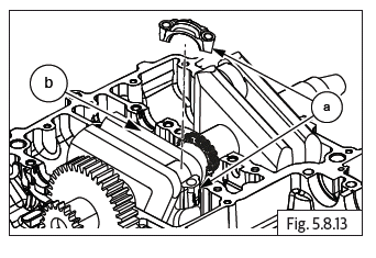
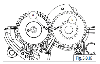
- Ensure the punch mark on the crankshaft gear (b) is towards the front of the upper crankcase.
- Locate balancer shaft in upper crankcase duly ensuring the punch mark on the gear (a) is aligned with the punch mark on the crankshaft gear.
- Ensure both the gears are meshed correctly.
Countershaft Assembly Sequence
NOTE
- Do not reuse thrust washers, circlips, collar bush. Always replace with new parts.
- Ensure all components are cleaned and lubricated with recommended lubricants before assembly.
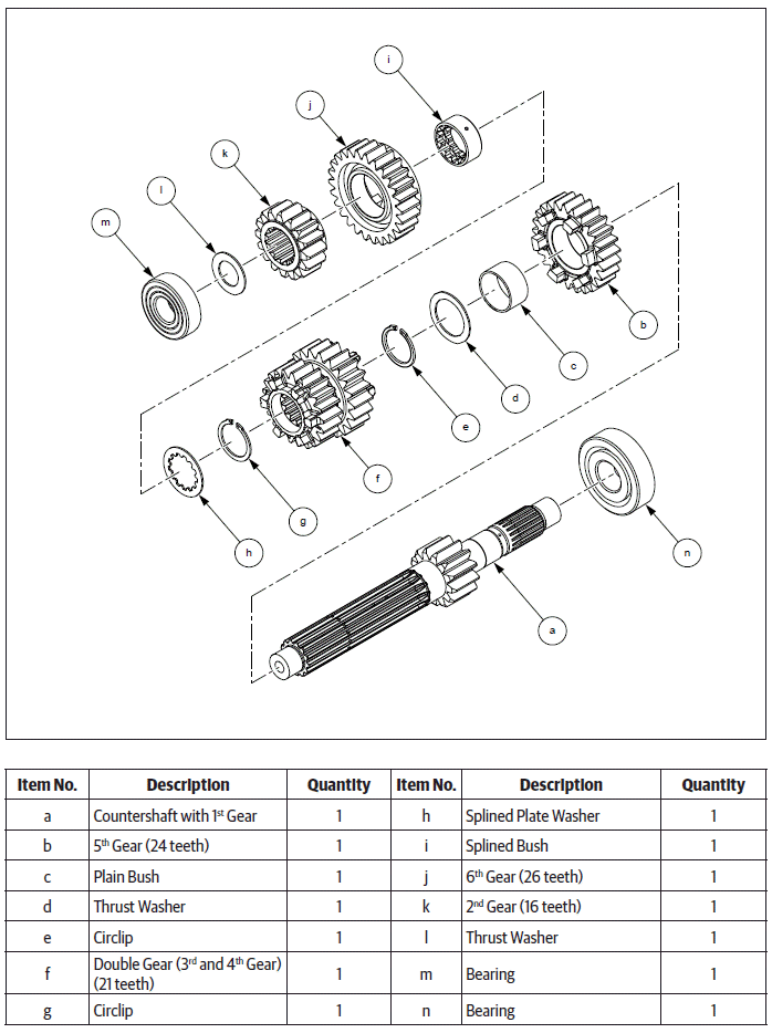
- The countershaft gears can be recognized by size: the gear with the smallest diameter is 2 nd gear, and the one with largest is 6 th gear. Ensure that all parts are put back in correct sequence and all circlips and washers are incorporated in correct places.
Countershaft Components
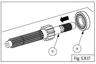
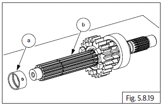
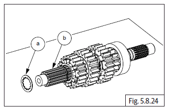
- Assemble ball bearing (a) on countershaft (b) from short end and ensure it is fully seated against the gear on driveshaft.
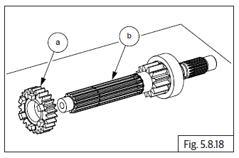
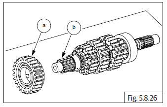
- Assemble 5 th gear (a) on countershaft (b) from longer end and ensure machined surface of gear is facing countershaft gear and lugs are facing outside.
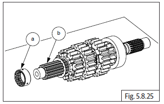
- Assemble plain bush (a) on countershaft (b).
- Ensure oil hole in plain bush is aligned with oil hole in countershaft.
NOTE
- Ensure bush is fully seated against 5 th gear on countershaft
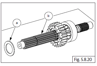
- Assemble 1 st plain thrust washer (a) on countershaft (b) and ensure it is fully seated against 5 th gear.
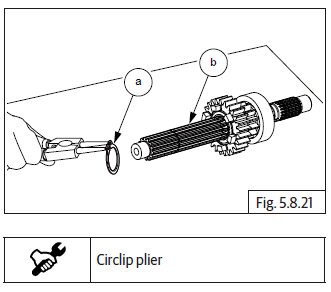
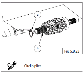
- Assemble 1 st circlip (a) on groove on countershaft (b) and ensure it is seated properly in the groove near 5 th gear.
- Gently rotate circlip without expanding to ensure it is properly seated.
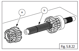
- Assemble 3 rd and 4 th (double gear) (a) on countershaft (b) such that the 4 th gear is facing the lugs on the 5 th gear.
- Assemble 2 nd circlip (a) on groove on countershaft (b) and ensure it is seated properly on groove.
- Assemble splined thrust washer (a) on counter- shaft (b) and ensure it is seated properly against circlip.
- Ensure oil hole in splined bush is aligned with oil hole in countershaft and assemble splined bush (a) on countershaft (b).
NOTE
- Ensure bush is fully seated against thrust washer on countershaft.
- Assemble 6 th gear (a) on countershaft (b) and ensure lugs are facing double gear.
- Assemble 2 nd gear (a) on countershaft (b).
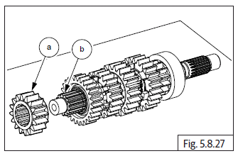
- Assemble thrust washer (a) on countershaft (b).
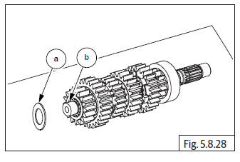
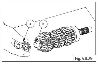
- Assemble ball bearing (a) on countershaft (b) and ensure it is properly seated against thrust washer on countershaft.
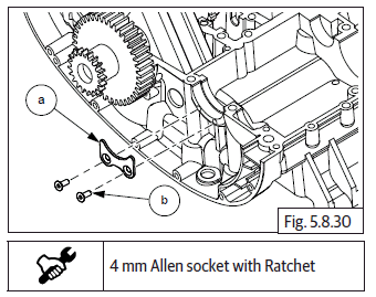
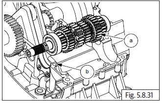
- Locate countershaft bearing stopper plate (a) and assemble 2 Nos. Hex head bolts (M5) (b).
- Assemble the countershaft assembly (a) with gears on the upper crankcase (b) with its splined end towards the RH side (clutch side).
- Ensure the two bearings are correctly seated in their respective housings.
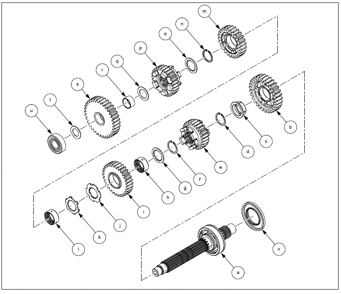
Driveshaft Assembly Sequence
See also:
 Royal Enfield Interceptor 650 - Service manual > Components Sub Assembly in Upper Crankcase
Crankshaft Journal Bearings NOTE In case the crankshaft is being resued, please Do not disturb OR remove the journal bearings from the crankcase. Refer journal bearing selection chart before installing journal bearings into crankcase. Ensure journal bearings are cleaned and well lubricated.
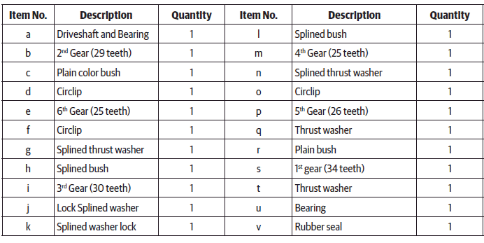
Royal Enfield Interceptor 650 - Service manual > Driveshaft Components
NOTE Do not resue thrust washers, circlips, collar bush. Always replace with new parts. Ensure each component is cleaned and lubricated with recommended lubricant. The driveshaft gears can be recognized by size: the gear with the smallest diameter is 6 th gear, and the one with largest is 1 st gear. Ensure that all parts are put back in correct sequence and all circlips and washers are incorporated in correct place.
 Rider's Manual BMW R 1250 GS GSA
 Owner's Manual Harley-Davidson Sportster XL1200X Forty-Eight
 Owner's Manual Honda CBR650R
 Service manual Honda CBR650
 Owner's Manual Honda PCX125
 Owner's Manual Kawasaki Z1000SX
 Service manual Kawasaki Z1000SX
 Owner's Manual Lexmoto Echo
 Owner's Manual Royal Enfield Interceptor 650
 Service manual Royal Enfield Interceptor 650
 Owner's Manual Yamaha MT-07