 Royal Enfield Interceptor 650 - Service manual > Driveshaft Components
NOTE
- Do not resue thrust washers, circlips, collar bush. Always replace with new parts.
- Ensure each component is cleaned and lubricated with recommended lubricant.
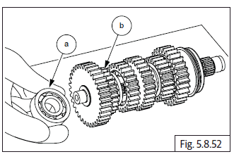
- The driveshaft gears can be recognized by size: the gear with the smallest diameter is 6 th gear, and the one with largest is 1 st gear. Ensure that all parts are put back in correct sequence and all circlips and washers are incorporated in correct place.
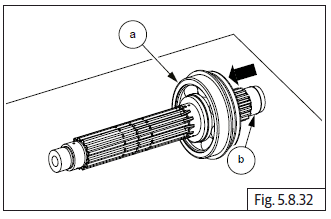
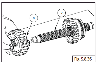
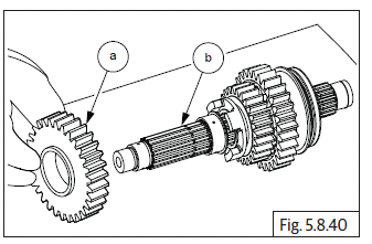
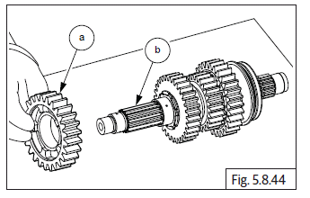
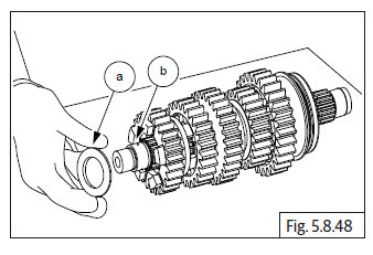
- Assemble ball bearing (a) on driveshaft (a) from short end and ensure it is fully seated against stopper on driveshaft.
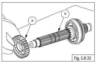
- Ensure machined surface of 2 nd gear is facing bearing and assemble 2 nd gear (a) on driveshaft (b) from the longer splines end.
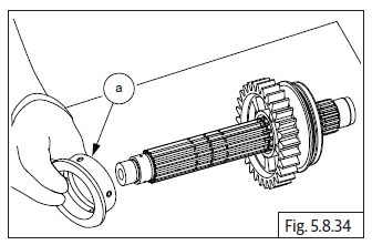
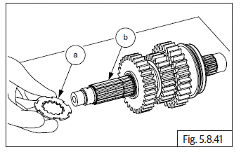
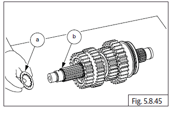
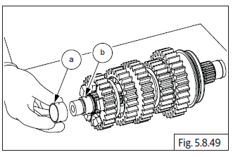
- Ensure collar on bush (a) is facing outside and assemble 2 nd gear collared bush on driveshaft. Ensure bush is seated properly inside 2 nd gear.
NOTE
- Ensure bush is seated properly inside 2 nd gear.
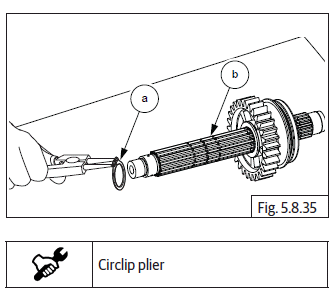
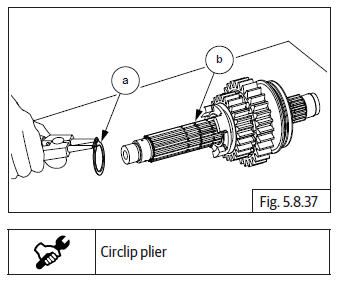
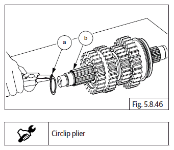
Assemble 1 st circlip (a) on innermost groove in driveshaft (b) and ensure it is seated properly on groove against 2 nd gear bush.
NOTE
- Gently rotate circlip without expanding to ensure it is properly seated in groove in driveshaft.
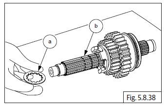
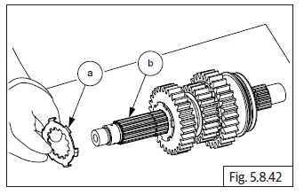
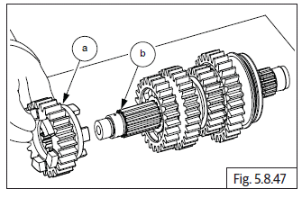
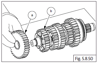
- Assemble 6 th gear (a) on driveshaft (b) ensuring lugs on larger face of gear are facing 2 nd gear.
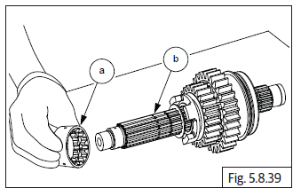
- Assemble 2 nd circlip (a) on inner groove on driveshaft (b) and ensure it is seated properly on groove.
NOTE
- Gently rotate circlip without expanding to ensure it is properly seated in groove in driveshaft.
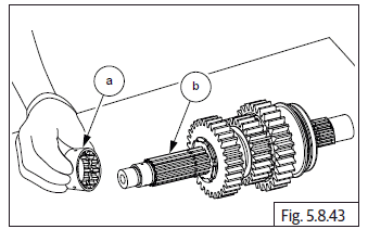
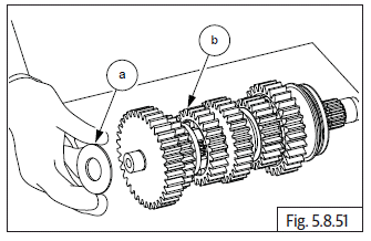
- Assemble splined thrust washer (a) on driveshaft (b) and ensure it is seated properly against circlip.
- Ensure oil hole in 1 st splined bush (a) is aligned with oil hole in driveshaft (b) and assemble splined bush on driveshaft.
NOTE
- Ensure bush is fully seated against thrust washer in driveshaft.
- Ensure collar on 3 rd gear (a) is facing outside and assemble 3 rd gear on driveshaft (b).
NOTE
- Ensure gear is fully seated on splined bush.
- Insert thrust lock washer (a) with internal and external splines on driveshaft (b) and align internal splines with groove in driveshaft.
- Rotate lock washer such that the washer locks in place on driveshaft and cannot come out.
- Assemble splined lock washer (a) on driveshaft (b) such that the outside tabs are facing the lock washer on driveshaft.
- Ensure outer tabs of lock washer are aligned and fully seated in outer splines of lock washer.
- Ensure oil hole in 2 nd splined bush (a) is aligned with oil hole in driveshaft (b) and assemble splined bush on driveshaft.
NOTE
- Ensure bush is fully seated against lock washer on driveshaft.
- Assemble 4 th gear (a) on the driveshaft (b) with its machined surface facing 3 rd gear and recessed lugs of 4 th gear facing outside.
- Ensure 4 th gear is seated fully on splined bush.
- Assemble 2 nd splined washer (a) on driveshaft (b) and ensure it is fully seated against 4 th gear.
NOTE
- Gently rotate circlip without expanding to ensure it is properly seated in groove in driveshaft.
- Assemble 3 rd circlip (a) on groove on driveshaft (b) and ensure circlip is properly seated in groove.
- Assemble 5 th gear (a) on driveshaft (b) with lugs facing 4 th gear.
- Assemble thrust washer (a) on driveshaft (b).
- Ensure oil hole in plain bush (a) is aligned with oil hole in driveshaft (b) and assemble plain bush on driveshaft.
NOTE
- Ensure the bush is fully seated against thrust washer on driveshaft.
- Ensure lugs seating surface of 1 st gear is facing lugs of 5 th gear; assemble 1 st gear (a) over bush on driveshaft (b). Ensure the 1 st gear is fully seated on bush.
- Assemble plain thrust washer (a) on driveshaft (b) and ensure it is fully seated against the 1 st gear.
- Assemble ball bearing (a) on driveshaft (b) and ensure it is properly seated against thrust washer on driveshaft.
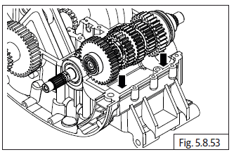
- Locate drive shaft assembly with gears on crankcase upper duly ensuring that the splines of the drive shaft are towards the LH side (Magneto side) of upper crankcase and the gears on counter shaft and drive shaft are properly meshed.
Journal bearings in lower crankcse
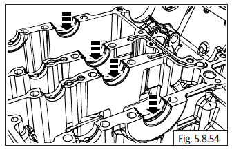
- Install crankshaft journal bearings into crankcase.
See also:
 Royal Enfield Interceptor 650 - Service manual > Connecting Rods
NOTE Ensure new journal bearings are located correctly in the connecting rods and caps. Connecting rod bolts are for one time use only. Do not reuse connecting rod bolts. Always replace them. Do not interchange connecting rod cap. Ensure the lug (a) in journal bearing is located in the grooves (b) on both connecting rod and cap is seated properly.
Royal Enfield Interceptor 650 - Service manual > Gear Shift Cam Drum
Assemble needle roller bearing (a) in lower crankcase (b) from the inside on LH side (Magneto side). Insert gear shift cam drum (c) into lower crankcase (b) from thr RH side (clutch side), duly ensuring the 2 pegs to the gear shift cam drum are towards the RH side (clutch side). Assemble big bearing (a) on lower crankcase RH side (b) (clutch side) over the gear shift cam drum. Gently tap on the bearing (a) to press fit with crankcase (b).
 Rider's Manual BMW R 1250 GS GSA
 Owner's Manual Harley-Davidson Sportster XL1200X Forty-Eight
 Owner's Manual Honda CBR650R
 Service manual Honda CBR650
 Owner's Manual Honda PCX125
 Owner's Manual Kawasaki Z1000SX
 Service manual Kawasaki Z1000SX
 Owner's Manual Lexmoto Echo
 Owner's Manual Royal Enfield Interceptor 650
 Service manual Royal Enfield Interceptor 650
 Owner's Manual Yamaha MT-07