 Royal Enfield Interceptor 650 - Service manual > Gear Shift Cam Drum
- Assemble needle roller bearing (a) in lower crankcase (b) from the inside on LH side (Magneto side).
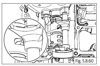
- Insert gear shift cam drum (c) into lower crankcase (b) from thr RH side (clutch side), duly ensuring the 2 pegs to the gear shift cam drum are towards the RH side (clutch side).
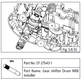
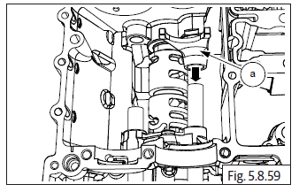
- Assemble big bearing (a) on lower crankcase RH side (b) (clutch side) over the gear shift cam drum.
- Gently tap on the bearing (a) to press fit with crankcase (b).
NOTE
- Ensure there is free rotation of gear shift cam drum.
Shifter fork
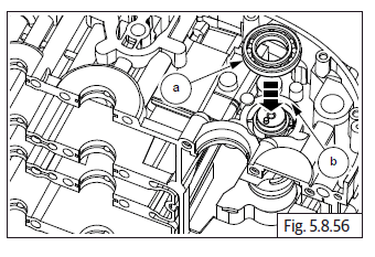
- Lubricate the 2 Nos. shifter fork spindles (a) and insert them into the lower crankcase from the RH side (Clutch side), till they are just protruding into the crankcase. Do not insert them fully.
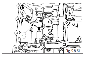
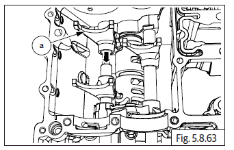
- Lubricate and position shifter fork marked "4", inside lower crankcase duly ensuring the small peg (a) on the fork is aligned to the central groove in the gear shift drum.
- Ensure the forks (a) are facing upwards.
- Ensure proper seating of the shifter fork peg in the groove in gear shift drum and press shifter fork spindle fully till it is seated into the boss in lower crankcase.
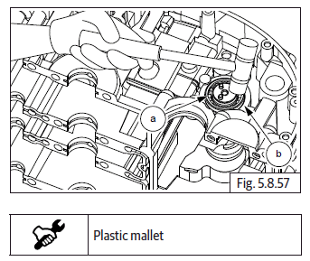
- Lubricate and position shifter fork marked "5" inside lower crankcase duly ensuring the small peg (a) on the fork is aligned to the outer slot in the gear shift drum. Ensure the forks are facing upwards.
- Ensure proper seating of the peg in gear shift drum and press the shifter fork spindle till it is protruding sufficiently outside shifter fork "5".
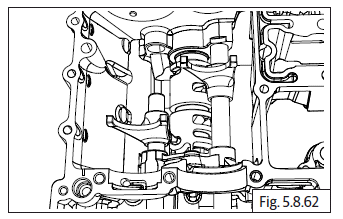
- Lubricate and position shifter fork marked "6" inside lower crankcase duly ensuring the small peg (a) on the fork is aligned to the slot in the extreme end of the gear shift drum. Ensure the forks are facing upwards.
- Ensure proper seating of the shifter fork pegs in the respective grooves in gear shift drum and press shifter fork spindle fully till it is seated into the boss in lower crankcase.
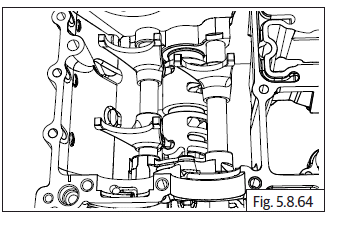
- Gently rotate gear shift drum to ensure proper seating of the pegs of all the shifter forks in the respective grooves in gear shift drum.
- Check for free rotation of the gear shift drum and movement of gear shift forks on the spindles.
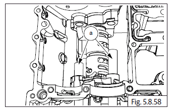
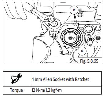
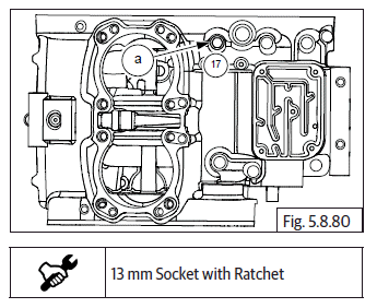
- Assemble bearing stopper plate (a) over the gear shift cam drum ball bearing on lower crankcase on the RH side (clutch side) and ensure the mounting holes are aligned.
- Locate 2 Nos. Hex socket head bolts (M5) (b) over the stopper plate and tighten to specified torque.
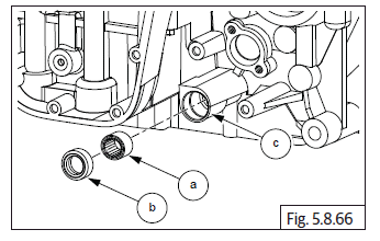
- Assemble bearing (a) and oil seal (b) in lower crankcase (c) on the LH side (magneto side).
Crankcases closing
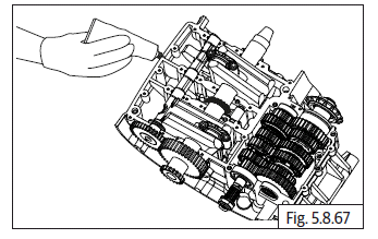
- Support upper crankcase assembly firmly on suitable wedges with the mating surface facing up.
NOTE
- Ensure the mating space both upper and lower crankcase are clean and dry.
- Ensure chain pad is located in the slot in upper crankcase.
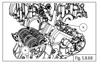
- Apply recommended liquid gasket evenly, on the upper crankcase mating surface.
- Ensure the 3 Nos. dowels (a) are located in the crankcase upper.
- Assemble lower crankcase over upper crankcase and ensure the following:
- The gear shifter forks are positoned in the respective grooves in the gears on mainshaft and countershaft (Rotate gear shifter drum to align the forks against the gears).
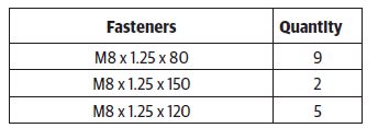
- A. Fasteners on Lower Crankcase
NOTE
- Apply recommended engine oil on the bolt threads and underneath the head of the bolts before inserting into crankcase.
- Ensure lower crankcase is seated fully and uniformly on upper crankcase without any gaps.
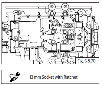
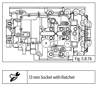
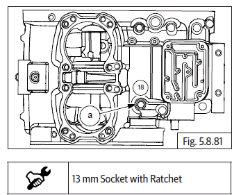
- Locate 4 Nos. Hex flange bolts M8 X 1.25 X 80 (a) in the mounting holes inside oil sump area in lower crankcase and hand tighten just sufficiently in the sequence shown. Do not TIGHTEN FULLY.
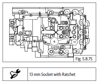
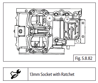
- Locate 2 Nos. Hex flange bolts M8 X 1.25 X 150 (a) in the mounting holes on the lower crankcase RH side (clutch side) and hand tighten just sufficiently in the sequence shown. Do not TIGHTEN FULLY.
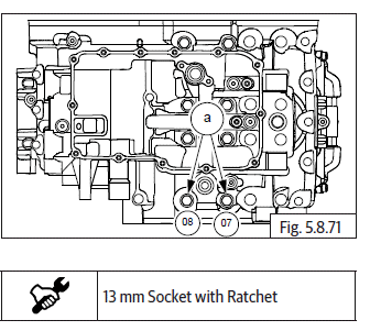
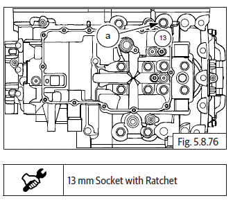
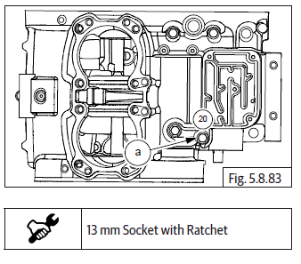
- Locate 2 Nos. Hex flange bolts M8 X 1.25 X 120 (a) in the mounting holes on the lower crankcase LH side (magneto side) and hand tighten just sufficiently in the sequence shown. Do not TIGHTEN FULLY.
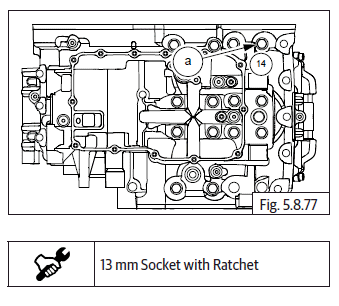
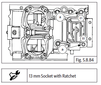
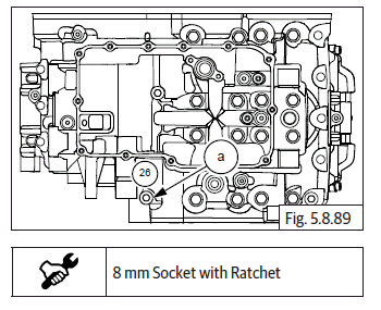
- Locate 1 No. Hex flange bolt M8 X 1.25 X 80 (a) in mounting hole inside oil sump area in lower crankcase and hand tighten just sufficiently. Do not TIGHTEN FULLY.
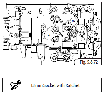
- Locate 1 No. Hex flange bolt M8 X 1.25 X 120 (a) in the hole in oil filter element area in lower crankcase front side and hand tighten just sufficiently. Do not TIGHTEN FULLY.
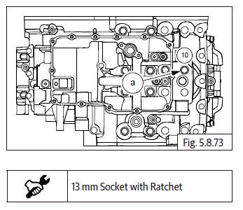
- Locate 1 No. Hex flange bolt M8 X 1.25 X 80 (a) in mounting hole inside oil sump area in lower crankcase and hand tighten just sufficiently. Do not TIGHTEN FULLY.
- Locate 1 No. Hex flange bolt M8 X 1.25 X 120 (a) in the hole in oil filter element area in lower crankcase front side and hand tighten just sufficiently. Do not TIGHTEN FULLY.
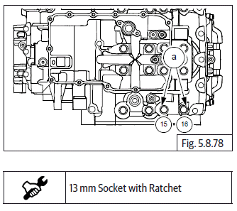
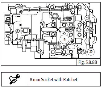
- Locate 1 No. Hex flange bolt M8 X 1.25 X 120 (a) in the mounting hole on the lower crankcase RH side (clutch side) and hand tighten just sufficiently. Do not TIGHTEN FULLY.
- Locate 1 No. Hex flange bolt M8 X 1.25 X 80 (a) in the mounting hole on the lower crankcase RH side (clutch side) and hand tighten just sufficiently. Do not TIGHTEN FULLY.
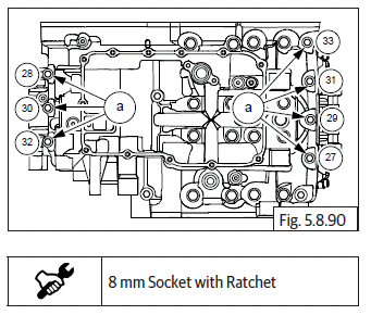
- Locate 2 Nos. Hex flange bolts M8 X 1.25 X 80 (a) in the mounting holes on the lower crankcase LH side (magneto side) and hand tighten just sufficiently. Do not TIGHTEN FULLY.
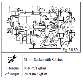
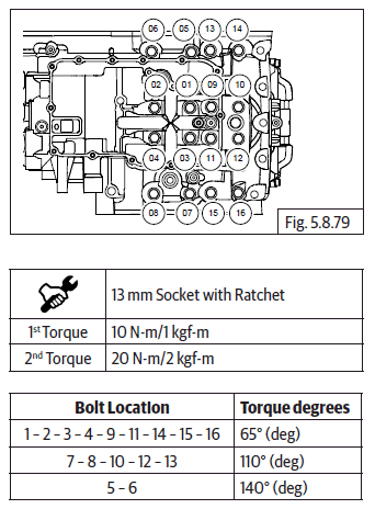
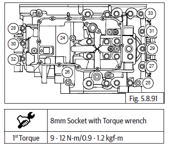
- Tighten the 16 Nos. Hex flange bolts M8 X 1.25, as mentioned in the
sequence below.
Initially the bolts are first torqued evenly.
Subsequently a second torque is applied evenly.
Finally angle torqued as specified below.
- B. Fasteners on upper Crankcase
- Gently invert the crankcase assembly such that the lower crankcase is resting firmly on suitable wedges.
- Locate 1 No. Hex flange bolt M8 X 1.25 X 105 (a) before oil filler hole area in upper crankcase RH side (clutch side) and hand tighten just sufficiently. Do not TIGHTEN FULLY.
- Locate 1 No. Hex flange bolt M8 X 1.25 X 45 (a) in the front mounting hole in the starter motor recess in upper crankcase LH side (magneto side) and hand tighten just sufficiently. Do not TIGHTEN FULLY.
- Locate 1 No. Hex flange bolt M8 X 1.25 X 105 (a) behind oil filler hole area in upper crankcase RH side (clutch side) and hand tighten just sufficiently. Do not TIGHTEN FULLY.
- Locate 1 No. Hex flange bolt M8 X 1.25 X 80 (a) in the rear mounting hole in the starter motor recess in upper crankcase LH side (magneto side) and hand tighten just sufficiently. Do not TIGHTEN FULLY.
- Locate 2 Nos. Hex flange bolt M8 X 1.25 X 80 (a) on the LH and RH sides of the breather box housing assembly in the rear end of upper crankcase and hand tighten just sufficiently. Do not TIGHTEN FULLY.
- Locate 1 No. Hex flange bolt M6 X 1 X 35 (a) at the rear end of upper crankcase RH side (Clutch side) and hand tighten just sufficiently. Do not TIGHTEN FULLY.
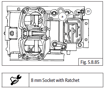
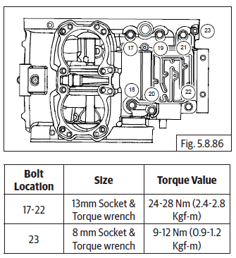
- Tighten the 7 Nos. Hex flange bolts on upper crankcase as mentioned in the sequence detailed below, to the specified torques.
- C. Fasteners on Lower Crankcase
- Gently invert the crankcase assembly such that the upper crankcase is resting firmly on suitable wedges.
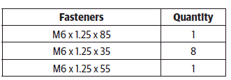
- Locate 1 No. Hex flange bolt M6 X 1 X 85 (a) in mounting hole inside oil sump area in lower crankcase and hand tighten just sufficiently. Do not TIGHTEN FULLY.
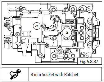
- Locate 1 No. Hex flange bolt M6 X 1 X 35 (a) in mounting hole the front LH side (magneto side) in lower crankcase and hand tighten just sufficiently. Do not TIGHTEN FULLY.
- Locate 1 No. Hex flange bolt M6 X 1 X 55 (a) in mounting hole on the LH side , behind magneto housing, in lower crankcase and hand tighten just sufficiently. Do not TIGHTEN FULLY.
- Locate 7 Nos. Hex flange bolts M6 X 1 X 35 (a) 4 Nos. bolts in the front mounting holes and 3 Nos. bolts in the rear mounting holes in lower crankcase and hand tighten just sufficiently. Do not TIGHTEN FULLY.
- Tighten the 10 Nos. Hex flange bolts , as mentioned in the sequence below,
See also:
 Royal Enfield Interceptor 650 - Service manual > Driveshaft Components
NOTE Do not resue thrust washers, circlips, collar bush. Always replace with new parts. Ensure each component is cleaned and lubricated with recommended lubricant. The driveshaft gears can be recognized by size: the gear with the smallest diameter is 6 th gear, and the one with largest is 1 st gear. Ensure that all parts are put back in correct sequence and all circlips and washers are incorporated in correct place.
Royal Enfield Interceptor 650 - Service manual > Oil Pressure Switch
Assemble oil pressure switch (a) along with washer (b) on crankcase. Do not TIGHTEN FULLY. Tighten oil pressure switch (a) to specified torque.
 Rider's Manual BMW R 1250 GS GSA
 Owner's Manual Harley-Davidson Sportster XL1200X Forty-Eight
 Owner's Manual Honda CBR650R
 Service manual Honda CBR650
 Owner's Manual Honda PCX125
 Owner's Manual Kawasaki Z1000SX
 Service manual Kawasaki Z1000SX
 Owner's Manual Lexmoto Echo
 Owner's Manual Royal Enfield Interceptor 650
 Service manual Royal Enfield Interceptor 650
 Owner's Manual Yamaha MT-07