 Royal Enfield Interceptor 650 - Service manual > Oil Pressure Switch
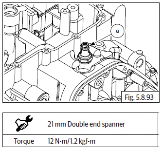
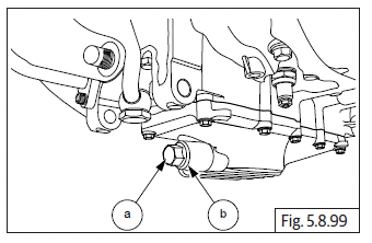
- Assemble oil pressure switch (a) along with washer (b) on crankcase. Do not TIGHTEN FULLY.

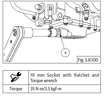
- Tighten oil pressure switch (a) to specified torque.
Oil Bypass
- Ensure O-rings (a) are located properly.
- Install oil bypass pipe (b) into lower crankcase oil gallery.
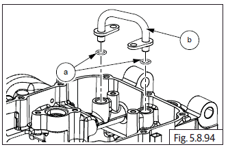
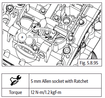
- Tighten 2 Nos. Hex socket head screw (M6) (a) to specified torque.
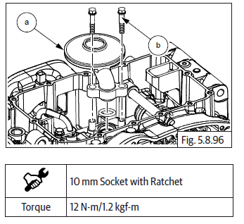
Oil Strainer
- Ensure O-ring is located properly.
- Install oil strainer (a) into lower crankcase oil gallery and tighten with 2 Nos. Hex flange head bolts (M6) (b) to specified torque.
Oil Pan
- Locate oil pan gasket (a) on crankcase and assemble oil pan (b).
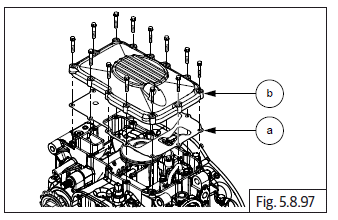
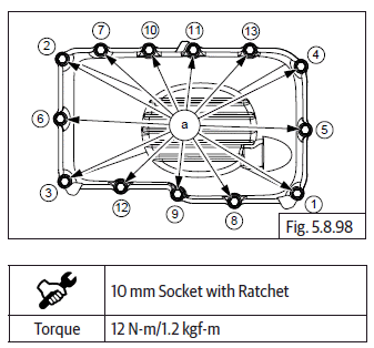
- Assemble and tighten 13 Nos. Hex flange head bolts (M6) (a) in crisscross pattern to specified torque.
NOTE
- Rotate the crankcase so that the connecting rods are facing upwards for further assembly.
- Support timing chain suitably to ensure it does not fall into the crankcase while rotating.
Drain Plug
- Assemble magnetic drain plug (M14) (a) along with washer (b).
- Tighten drain plug (a) to specified torque.
Pistons and Rings
NOTE
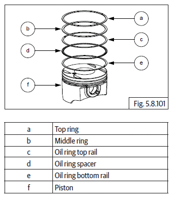
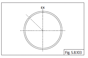
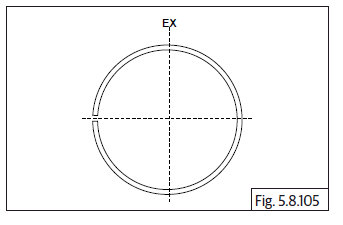
- Rings should be assembled with proper orientation (top marking should be always towards 1 st ring end gap should be 45º before "EX" mark on piston crown).
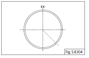
- Middle 2 nd ring end gap should be 180º from 1 st ring end gap.
- Oil ring 3 rd top rail end gap should be 180º from 2nd ring end gap (45º before "EX" on piston crown).
- Oil ring spacer end gap should be 45º before 3 rd ring top rail end gap (90º before "EX" on piston crown).
- Oil ring (3 rd ) bottom rail end gap should be 180º from 3 rd ring top rail end gap.
- One of the circlip should be assembled on the inner side of piston.
Piston Rings
Orientation Pattern
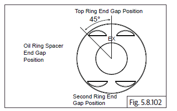
- Top ring (1 st ) and oil ring (3 rd ) top rail end gap positions.
- Middle (2 nd ) ring and oil ring (3 rd ) bottom rail end gap positions.
- Oil ring spacer end gap position.
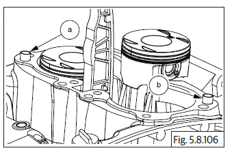
Cylinder Barrel Dowels on Crankcase
- Install 2 Nos. dowel pins (a) and (b) on upper crankcase.
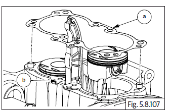
Cylinder Barrel Gasket on Crankcase
- Ensure the gasket seating area in crankcase is clean.
- Ensure cam chain is routed through a new cylinder base gasket (a) and locate the gasket on crankcase (b).
- Ensure proper seating of the gasket on the dowels on the crankcase.
Piston LH in Cylinder Barrel
- Ensure piston LH is at its top most position by rotating crankshaft clockwise.
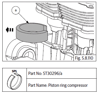
- Locate special tool (a) on piston LH.
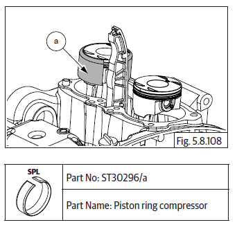
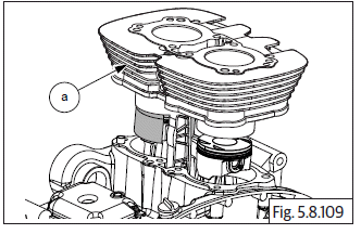
- Position and hold cylinder barrel above crankcase, route cam chain through cylinder barrel bottom and ensure it is supported firmly and suitably at the top.
- Ensure cylinder barrel LH is well lubricated, LH piston is held firmly and straight.
- Gently lower cylinder barrel (a) over the special tool piston LH, till the piston is halfway into the cylinder barrel.
- Hold cylinder barrel firmly in suspended position and remove the special tool (a) from piston LH.
See also:
 Royal Enfield Interceptor 650 - Service manual > Gear Shift Cam Drum
Assemble needle roller bearing (a) in lower crankcase (b) from the inside on LH side (Magneto side). Insert gear shift cam drum (c) into lower crankcase (b) from thr RH side (clutch side), duly ensuring the 2 pegs to the gear shift cam drum are towards the RH side (clutch side). Assemble big bearing (a) on lower crankcase RH side (b) (clutch side) over the gear shift cam drum. Gently tap on the bearing (a) to press fit with crankcase (b).
Royal Enfield Interceptor 650 - Service manual > Piston RH in Cylinder Barrel
Ensure cylinder barrel RH is well lubricated, RH piston is at its top most position, held firmly and straight. Locate special tool over piston RH. Gently lower cylinder barrel (a) till piston RH is halfway into the cylinder barrel. Hold cylinder barrel firmly in suspended position and remove the special tool (a) from piston RH. Gently lower cylinder barrel further, till it is firmly seated on the crankcase. Locate 2 Nos. dowel pins (a) on cylinder barrel and ensure they are seated properly.
 Rider's Manual BMW R 1250 GS GSA
 Owner's Manual Harley-Davidson Sportster XL1200X Forty-Eight
 Owner's Manual Honda CBR650R
 Service manual Honda CBR650
 Owner's Manual Honda PCX125
 Owner's Manual Kawasaki Z1000SX
 Service manual Kawasaki Z1000SX
 Owner's Manual Lexmoto Echo
 Owner's Manual Royal Enfield Interceptor 650
 Service manual Royal Enfield Interceptor 650
 Owner's Manual Yamaha MT-07