 Royal Enfield Interceptor 650 - Service manual > Piston RH in Cylinder Barrel
- Ensure cylinder barrel RH is well lubricated, RH piston is at its top most position, held firmly and straight.
- Locate special tool over piston RH.
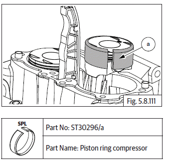
- Gently lower cylinder barrel (a) till piston RH is halfway into the cylinder barrel.
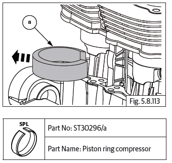
- Hold cylinder barrel firmly in suspended position and remove the special tool (a) from piston RH.
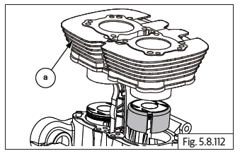
- Gently lower cylinder barrel further, till it is firmly seated on the crankcase.
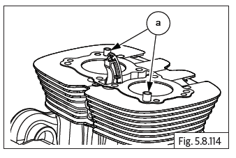
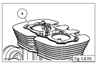
- Locate 2 Nos. dowel pins (a) on cylinder barrel and ensure they are seated properly.
Cylinder Head Gasket on Cylinder Barrel
- Ensure the gasket seating surface on cylinder barrel is clean.
- Ensure4 cam chain is routed through a new cylinder head gasket.
- Locate new head gasket (a) on cylinder barrel and ensure it is properly seated on the dowel pins and cylinder barrel.
Floating Chain Pad
- Hold timing chain (a) suitably and insert chain pad (b) into cylinder barrel with the chain contact area facing inside.
CAUTION Ensure floating chain pad seating correctly in the crankcase and free radial movement.
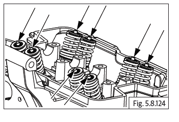
Components in Cylinder Head
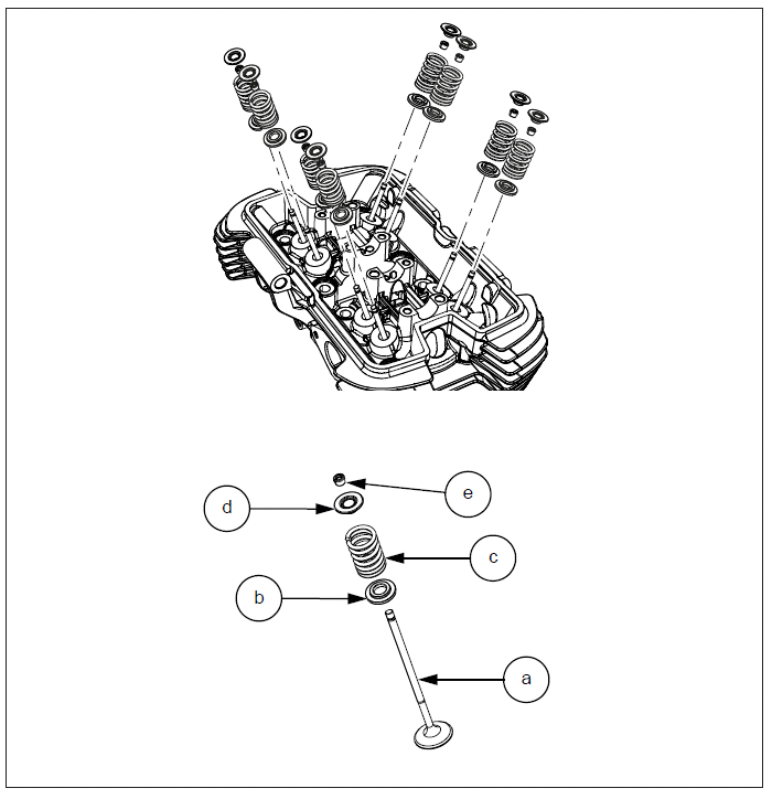
Components in Cylinder Head
Valves and Springs
- Install 8 Nos. valve stem seals (b) on the 8 Nos. valve guides (a).
- Lubricate and insert the valves (a) into the valve guides inside cylinder head (b).
- Support the valve inside cylinder head and assemble valve spring (a) over valve stem (b) in the outer area of the cylinder head.
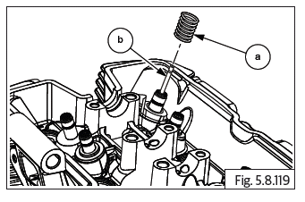
- Insert collar (a) above valve spring (b).
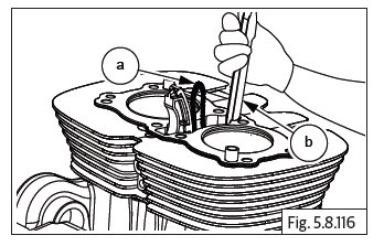
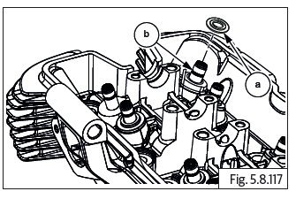
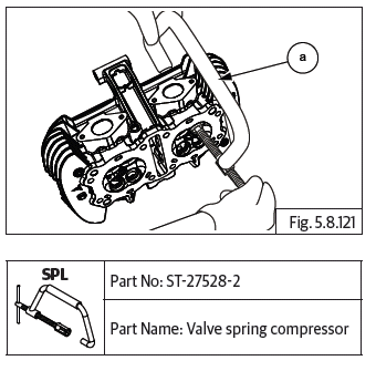
- Locate special tool on the valve such that the threaded screw end of the tool is seated centrally on the valve inside the cylinder head and the other end is seated on the valve spring collar on the outer side of the cylinder head.
- Compress valve spring with special tool (a) by "hand tightening" the threaded screw of the special tool gently, till it locks against the valve.
CAUTION Do not overtighten the special tool as it will damage both the valve seating surface and the special tool.
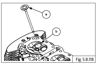
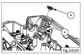
- Locate two split cotters (a) on the collar with their tapered end facing inside and the flat edges seated against the valve stem top portion.
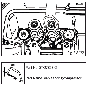
- Gently and slowly release special tool by unscrewing the threaded shaft, duly ensuring the valve cotters are locked in place on the valve stem and the tapered surfaces of the cotters are inside the valve spring collar.
- Remove special tool (a) from the valve.
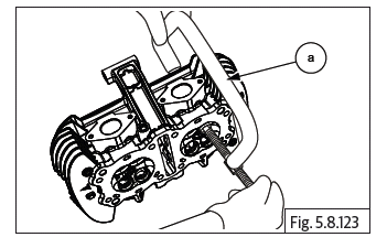
- Repeat the above process to install the other seven valves, springs, collars and cotters on the cylinder head.
See also:
 Royal Enfield Interceptor 650 - Service manual > Oil Pressure Switch
Assemble oil pressure switch (a) along with washer (b) on crankcase. Do not TIGHTEN FULLY. Tighten oil pressure switch (a) to specified torque.
Royal Enfield Interceptor 650 - Service manual > Cylinder Head on Cylinder Barrel
Cylinder head assembly on cylinder barrel Position cylinder head over the barrel such that the exhaust ports are facing towards the front and inlet ports are towards the rear of the engine. Ensure the 2 Nos. dowels (a) and cylinder head gasket are located on the cylinder barrel. Ensure the cam chain pads are positioned correctly and route the cam chain from the lower side of the cylinder head to the top. Support cam chain suitably to prevent it from falling into cylinder head.
 Rider's Manual BMW R 1250 GS GSA
 Owner's Manual Harley-Davidson Sportster XL1200X Forty-Eight
 Owner's Manual Honda CBR650R
 Service manual Honda CBR650
 Owner's Manual Honda PCX125
 Owner's Manual Kawasaki Z1000SX
 Service manual Kawasaki Z1000SX
 Owner's Manual Lexmoto Echo
 Owner's Manual Royal Enfield Interceptor 650
 Service manual Royal Enfield Interceptor 650
 Owner's Manual Yamaha MT-07