 Royal Enfield Interceptor 650 - Service manual > Cylinder Head on Cylinder Barrel
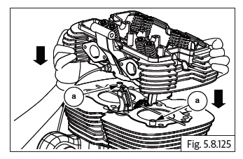
Cylinder head assembly on cylinder barrel
- Position cylinder head over the barrel such that the exhaust ports are facing towards the front and inlet ports are towards the rear of the engine.
- Ensure the 2 Nos. dowels (a) and cylinder head gasket are located on the cylinder barrel.
- Ensure the cam chain pads are positioned correctly and route the cam chain from the lower side of the cylinder head to the top.
- Support cam chain suitably to prevent it from falling into cylinder head.
CAUTION Cylinders bolts are pre-coated and hence should be used one time only. Do not reuse.
- Locate new 8 Nos. Hex flange head bolts (M10) (a) along with washers on the cylinder head.
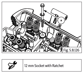
- Tighten the cylinder head bolts in a crisscross pattern to the initial 1 st torque values FIRST and then to the 2 nd torque values as specified below.
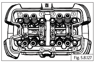
- Finally tighten each of the cylinder head bolts using an angular torque wrench, to the specified angular torque value given below and in the same crisscross pattern detailed above.
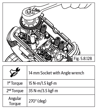
CAUTION Torque and angle should be as specified. Do not provide over-torque as it will damage the bolts.
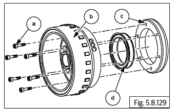
Starter Clutch to Magneto Rotor
- Lubricate starter clutch (d) and assemble into outer ring (c) with the collar seating in the groove in the outer ring.
- Position outer ring on magneto rotor such that the collar of the starter clutch is facing magneto rotor.
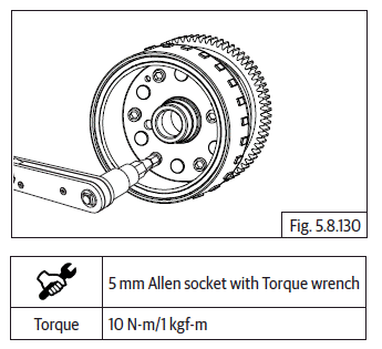
- Ensure mounting holes are aligned, insert 6 Nos. Hex socket head screws (M6) (a) into magneto rotor (b) and tighten outer ring (c) to rotor to specified torque.
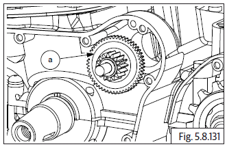
Ideal Gear in Crankcase LH
- Position idle gear (a) against crankcase with smaller gear facing outside and insert idle gear spindle into boss in crankcase.
Woodruf Key on Crankshaft
- Assemble woodruff key (a) on crankshaft and ensure it is facing upwards by rotating crankshaft.
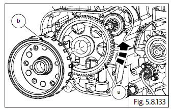
Magneto Rotor on Crankcase
- Position gear starter clutch with the collar facing outside.
- Insert gear starter clutch (a) into magneto rotor (b) and rotate anti-clockwise to lock the gear starter clutch into magneto rotor.
- Locate magneto rotor (a) on crankshaft duly ensuring the slot in the rotor is positioned correctly on woodruff key.
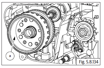
- Locate and assemble Hex flange bolt (M12) (a) with washer on magneto rotor and tighten bolt just sufficiently.
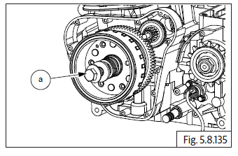
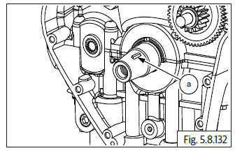
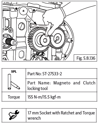
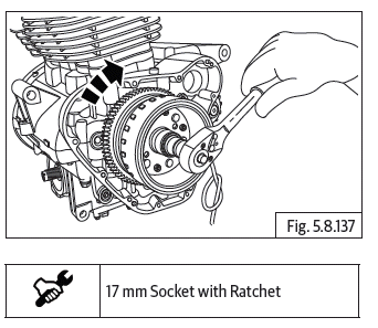
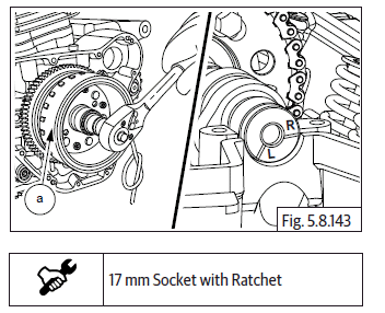
- In order to tighten magneto rotor bolt, Insert special tool (a) in crankcase RH to lock the crankshaft and prevent rotation.
- Ensure LH piston is at TDC on compression stroke before locating special tool inside crankcase RH.
- Remove special tool from crankcase RH side after tightening magneto rotor bolt.
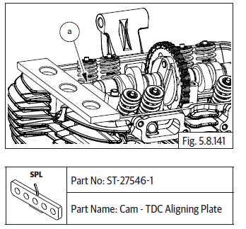
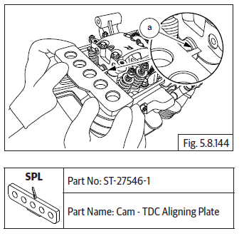
Camshaft Sub-Assembly
- Hold the timing chain in stretched condition and gently rotate crankshaft clockwise to bring LH piston to TDC.
CAUTION Do not rotate crankshaft anti-clockwise.
- Hold sprocket in position with one of the slotted holes facing on top.
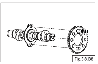
- Assemble cam chain (a) on sprocket and locate camshaft (b) into sprocket from the RH side.
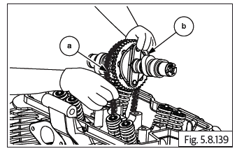
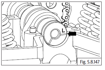
- Ensure reference mark "L" in the camshaft is aligned to the cylinder head on LH side.
- Ensure the flat edge of the special tool (a) is correctly located in the slot on the camshaft on RH side and the tool is resting correctly on the cylinder head.
- Gently rotate crankshaft to ensure proper seating of the tool in the camshaft slot and cylinder head.
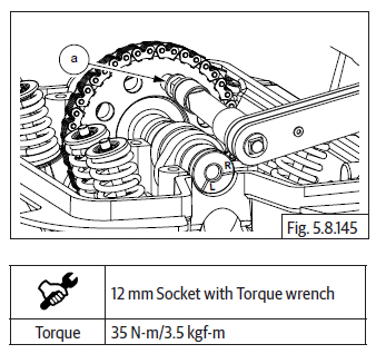
- Locate timing chain sprocket on camshaft with its mounting slot centralised to the threads in the camshaft.
- Locate and tighten Hex head bolt (M8) (a) sufficiently on timing chain sprocket. Do not TIGHTEN FULLY.
- Remove the special tool from the camshaft on RH side.
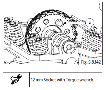
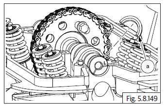
- Rotate magneto (a) till another slotted hole on cam chain sprocket is at top most position. Ensure reference mark "R" aligned to the cylinder head.
- Ensure the angular edge of the special tool (a) is correctly located in the slot on the camshaft on RH side and the tool is resting correctly on the cylinder head.
- Gently rotate camshaft, if necessery, to ensure proper seating of the tool in the camshaft slot and cylinder head.
- Tighten Hex head bolt (M8) (a) to specified torque.
- Remove the special tool from cylinder head on RH side.
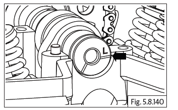
- Rotate the magneto (a) clockwise till the first bolt is visible at top most position on cam side sprocket.
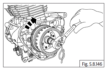
- Ensure reference mark "L" in the camshaft is aligned to the cylinder head on LH side.
- Tighten Hex head bolt (M8) (a) to specified torque.
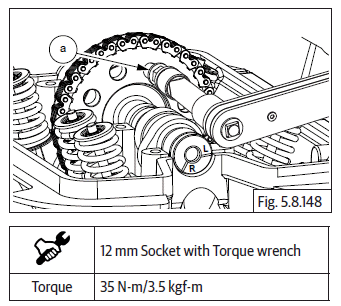
- Locate and fit "C" washer (a) on camshaft.
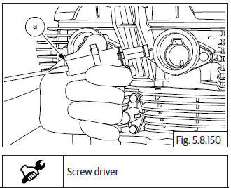
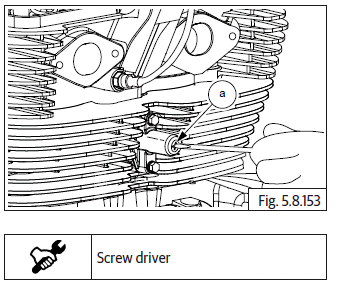
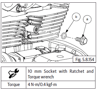
Timing Chain Tensioner
- Ensure center bolt is removed from timing chain tensioner.
- Insert screw driver into timing chain tensioner adjuster (a) and loosen screw completely to release spring tension.
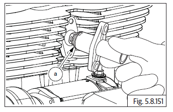
- Assemble new gasket on chain tensioner adjuster (a). Ensure the foot is fully retracted into chain tensioner and locate chain tensioner adjuster in cylinder barrel such that the longer side of the foot is facing towards cylinder barrel RH.
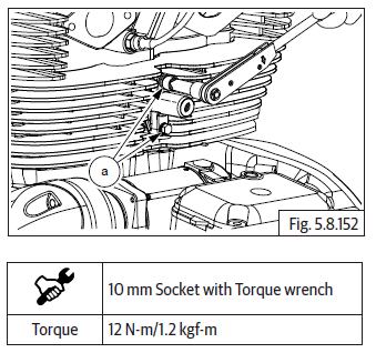
- Assemble 2 Nos. Hex flange head bolt (M6) (a) on chain tensioner adjuster and tighten to specified torque.
- Locate screw driver into chain tensioner adjuster (a) and tighten tensioner screw till it comes to a stop. DO NOT OVER TIGHTEN.
- Locate new O-ring (b) and, assemble Hex flange head bolt (M6) (a) on chain tensioner adjuster and tighten fully to specified torque.
See also:
 Royal Enfield Interceptor 650 - Service manual > Piston RH in Cylinder Barrel
Ensure cylinder barrel RH is well lubricated, RH piston is at its top most position, held firmly and straight. Locate special tool over piston RH. Gently lower cylinder barrel (a) till piston RH is halfway into the cylinder barrel. Hold cylinder barrel firmly in suspended position and remove the special tool (a) from piston RH. Gently lower cylinder barrel further, till it is firmly seated on the crankcase. Locate 2 Nos. dowel pins (a) on cylinder barrel and ensure they are seated properly.
Royal Enfield Interceptor 650 - Service manual > Rocker Arms in Carriers LH and RH
Exhaust rocker arm in carrier "L" Place the carrier (a) on a work table with the mark "L" facing upwards. Gently depress the spring (a) and install into rocker carrierrs (b). Locate rocker arm (b) with the marking "EL" into carrier "L" duly ensuring the following. The roller of the rocker arm is inserted from the side marked "L". The tappet adjustment screws are facing upwards. Ensure the holes are aligned and insert spindle with its small chamfer side in the carrier. Ensure cut away in spindle is correctly aligned to the carrier mounting hole. Align and insert the spindle (c) into rocker carrier and rocker arm.
 Rider's Manual BMW R 1250 GS GSA
 Owner's Manual Harley-Davidson Sportster XL1200X Forty-Eight
 Owner's Manual Honda CBR650R
 Service manual Honda CBR650
 Owner's Manual Honda PCX125
 Owner's Manual Kawasaki Z1000SX
 Service manual Kawasaki Z1000SX
 Owner's Manual Lexmoto Echo
 Owner's Manual Royal Enfield Interceptor 650
 Service manual Royal Enfield Interceptor 650
 Owner's Manual Yamaha MT-07