 Kawasaki Z1000SX - Service manual > Crankcase Splitting
Crankcase Splitting
- Remove the engine (see Engine Removal in the Engine Removal/Installation chapter).
- Set the engine on a clean surface and hold the engine steady while parts are being removed.
- Remove:
Cylinder (see Cylinder Removal in the Engine Top End chapter)
Clutch (see Clutch Removal in the Clutch chapter)
External Shift Mechanism (see External Shift Mechanism Removal)
Starter Motor (see Starter Motor Removal in the Electrical System chapter)
Oil Pump (see Oil Pump Removal in the Engine Lubrication System chapter)
Alternator Rotor (see Alternator Rotor Removal in the Electrical System chapter)
Oil Filter (see Oil Filter Replacement in the Periodic Maintenance chapter)
Oil Cooler (see Oil Cooler Removal in the Engine Lubrication System chapter)
Oil Pipe (see Oil Pipe Removal in the Engine Lubrication System chapter)
Oil Pressure Relief Valve (see Oil Pressure Relief Valve Removal in the Engine Lubrication System chapter)
If the crankshaft is to be removed, remove the pistons (see Piston Removal in the Engine Top End chapter).
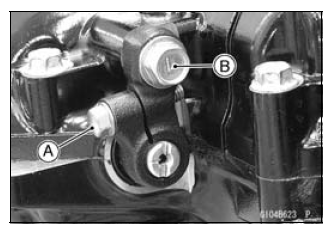
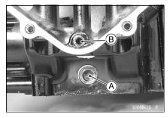
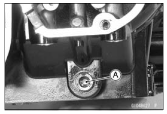
- Remove:
Balancer Shaft Clamp Bolt [A]
Balancer Shaft Clamp Lever Bolt [B]
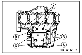
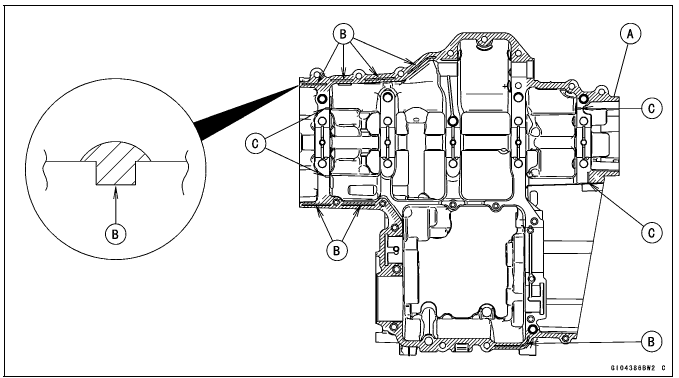
- Remove the upper crankcase bolts following the specified sequence.
- First, loosen the M6 bolts [A].
- Second, loosen the M7 bolts [B].
- Lasty, loosen the M8 bolts [C].
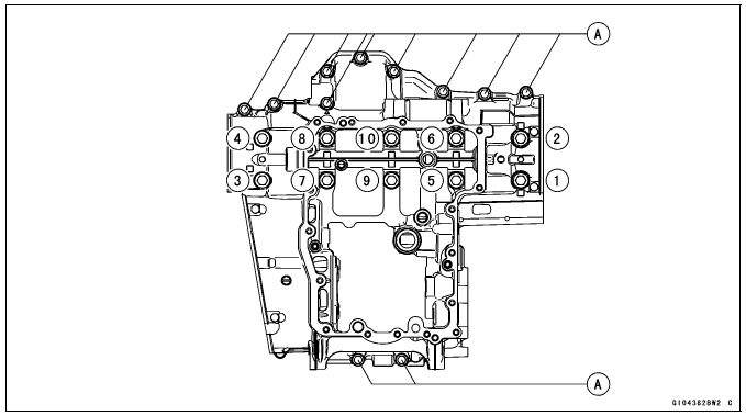
- Remove the lower crankcase bolts, following the specified sequence.
- First, loosen the M7 bolts [A].
- Lastly, loosen the M9 bolts as shown sequence [1 - 10] in the figure.
- Tap lightly around the crankcase mating surface with a plastic mallet,
and split the crankcase.
- Take care not to damage the crankcase.
Crankcase Assembly
NOTICE The upper and lower crankcase halves are machined at the factory in the assembled state, so the crankcase halves must be replaced as a set.
- With a high-flash point solvent, clean off the mating surfaces of the crankcase halves and wipe dry.
- Using compressed air, blow out the oil passages in the crankcase halves.
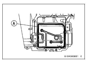
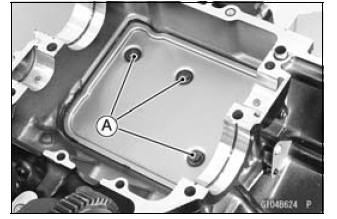
- Apply liquid gasket to the breather plate mating surface [A] 1 mm (0.04
in.) or more thick, and then install the breather plate.
- Using a high-flash point solvent, clean off any oil or dirt that may be on the liquid gasket coating area. Dry them with a clean cloth.
Sealant - Liquid Gasket, TB1207B: 92104-2068
NOTE
- Make the application finish within 7 minutes when the liquid gasket to the mating surface of the breather plate is applied.
- Moreover fit the plate and tighten the bolts just after application of the liquid gasket.
- Apply a non-permanent locking agent to the threads of the breather plate
bolts [A] and tighten them.
Torque - Breather Plate Bolts: 9.8 N*m (1.0 kgf*m, 87 in*lb)
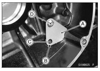
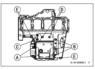
- Install the breather side plate [A] so that the plate hole [B] fit the projection [C] of the upper crankcase.
- Apply a non-parmanent locking agent to the threads of the breather side
plate bolt [D] and tighten it.
Torque - Breather Side Plate Bolt: 5.9 N*m (0.60 kgf*m, 52 in*lb)
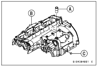
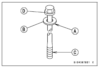
- Press and insert the fitting [A] in the upper crankcase [B] until it is
bottomed.
Special Tool - Bearing Driver Set: 57001-1129
- Press and insert the plug [C] in the upper crankcase so that the plug is deeper than crankcase surface.
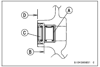
- Press and insert the new needle bearing [A] for the shift shaft so that its marked side faces outside and its surface [B] is flush with the end of the hole.
- Install the new oil seal [C] so that its surface [D] is flush with the end of the hole.
- Apply grease to the oil seal lips.
- Apply a non-parmanent locking agent to the oil passage plugs [A], and
tighten them.
Torque - Oil Passage Plugs: 20 N*m (2.0 kgf*m, 15 ft*lb)
- Install the oil passage plug [B] in the lower crankcase, and tighten it.
Torque - Oil Passage Plug: 9.8 N*m (1.0 kgf*m, 87 in*lb)
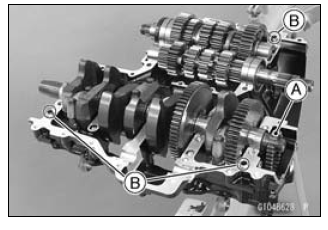
- Install:
Crankshaft (see Crankshaft Installation)
Connecting Rods (see Connecting Rod Installation)
Camshaft Chain [A]
Transmission Shafts and Gears (see Transmission Shaft Installation)
Dowel Pins [B]
Shift Drum (see Shift Drum and Fork Installation)
Shift Forks and Shift Rods (see Shift Drum and Fork Installation) - Before fitting the lower case on the upper case, check the following.
- Be sure to hang the camshaft chain on the crankshaft.
- Check to see that the shift drum and transmission gears are in the neutral position.
- Apply liquid gasket [A] to the mating surface of the lower crankcase
half.
- Using a high-flash point solvent, clean off any oil or dirt that may be on the liquid gasket coating area. Dry them with a clean cloth.
Sealant - Liquid Gasket, TB1216B: 92104-1064
NOTE
- Especially, apply a sealant so that it shall be filled up on the grooves [B].
- Do not apply liquid gasket to the inside of the groove [C].
NOTICE Do not apply liquid gasket around the crankshaft main bearing inserts and oil passage holes.
- Fit the lower crankcase to the upper crankcase.
NOTE
- Make the application finish within 20 minutes when the liquid gasket to the mating surface of the crankcase half is applied.
- Moreover fit the case and tighten the bolts just after application of the liquid gasket.
- The M9 bolts have copper plated washers, replace them with new ones.
- Apply molybdenum disulfide oil solution to the lower seating surface [A] on the copper plated washer [B] and threads [C] of the M9 bolts [D].
- Tighten the lower crankcase bolts using the following steps.
- Following the sequence numbers on the lower crankcase half, tighten
theM9 bolts [1 - 10] with copper plated washers.
Torque - Crankcase Bolts (M9): 42 N*m (4.2 kgf*m, 31 ft*lb)
- Tighten the M7 bolts [A].
Torque - Crankcase Bolts (M7): 20 N*m (2.0 kgf*m, 15 ft*lb)
- Following the sequence numbers on the lower crankcase half, tighten
theM9 bolts [1 - 10] with copper plated washers.

- Tighten the upper crankcase bolts follow in the specified sequence.
- First, tighten the M8 bolts [A].
Torque - Crank Case Bolts (M8): 27 N*m (2.8 kgf*m, 20 ft*lb)
- Second, tighten the M7 bolts.
L = 85 mm (3.35 in.) [B]
L = 50 mm (1.97 in.) [C]
Torque - Crank Case Bolts (M7): 20 N*m (2.0 kgf*m, 15 ft*lb) - Lasty, tighten the M6 bolts.
L = 68 mm (2.69 in.) [D]
L = 40 mm (1.57 in.) [E]
Torque - Crank Case Bolts (M6): 12 N*m (1.2 kgf*m, 106 in*lb)
- First, tighten the M8 bolts [A].
- After tightening all crankcase bolts, check the following items.
- Wipe up the liquid gasket that seeps out around the crankcase mating surface.
- Crankshaft and transmission shafts turn freely.
- While spinning the output shaft, gears shift smoothly from the 1st to 6th gear, and 6th to 1st.
- When the output shaft stays still, the gear can not be shifted to 2nd gear or other higher gear positions.
- Install the removed parts (see appropriate chapters).

 Rider's Manual BMW R 1250 GS GSA
 Owner's Manual Harley-Davidson Sportster XL1200X Forty-Eight
 Owner's Manual Honda CBR650R
 Service manual Honda CBR650
 Owner's Manual Honda PCX125
 Owner's Manual Kawasaki Z1000SX
 Service manual Kawasaki Z1000SX
 Owner's Manual Lexmoto Echo
 Owner's Manual Royal Enfield Interceptor 650
 Service manual Royal Enfield Interceptor 650
 Owner's Manual Yamaha MT-07