 Honda CBR650 - Service manual > Drive chain slider
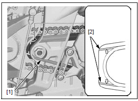
Check the drive chain slider [1] for wear or damage.
The drive chain slider must be replaced if it is worn to the wear limit lines [2].
BRAKE FLUID
NOTICE
Spilled fluid can damage painted, plastic or rubber parts. Place a rag over these parts whenever the system is serviced.
NOTE:
- Do not mix different types of fluid, as they are not compatible with each other.
- Do not allow foreign material to enter the system when filling the reservoir.
- When the fluid level is low, check the brake pads for wear.
A low fluid level may be due to wear of the brake pads. If the brake pads are worn and caliper pistons are pushed out, this accounts for a low fluid level. If the brake pads are not worn and fluid level is low, check the entire system for leaks.
FRONT BRAKE
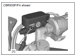
Turn the handlebar so the reservoir is level and check the front brake fluid level through the sight glass.
If the level is near the "LOWER" level line [1], fill the brake fluid as follows.
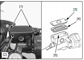
Remove the following:
- Two screws [1]
- Reservoir cap [2]
- Set plate [3]
- Diaphragm [4]
Fill the reservoir with DOT 4 brake fluid from a sealed container to the upper level line (casting ledge) [5].
Install the diaphragm, set plate and reservoir cap, and tighten the screws to the specified torque.
TORQUE: 1.5 N*m (0.2 kgf*m, 1.1 lbf*ft)
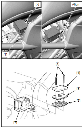
REAR BRAKE
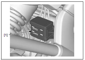
Support the motorcycle upright position on a level surface and check the rear brake fluid level.
If the level is near the "LOWER" level line [1], fill the brake fluid as follows.
Loosen the reservoir stay bolt [1].
Slightly pull the reservoir [2] upward and turn it counterclockwise.
Align the groove with the tab, then temporarily tighten the reservoir stay bolt.
Take care not to spill the fluid out of the reservoir.
Remove the following:
- Two screws [3]
- Reservoir cap [4]
- Set plate [5]
- Diaphragm [6]
Fill the reservoir with DOT 4 brake fluid from a sealed container to the upper level line [7].
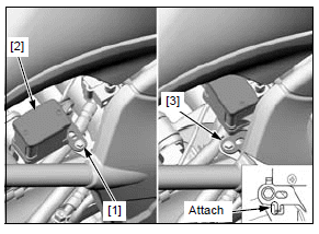
Install the diaphragm, set plate, reservoir cap and tighten the screws to the specified torque.
TORQUE: 1.5 N*m (0.2 kgf*m, 1.1 lbf*ft)
Loosen the reservoir stay bolt [1] and set the reservoir [2] in position.
Attach the stopper of the reservoir stay [3] against the groove surface, then tighten the reservoir stay bolt securely.
BRAKE PADS WEAR
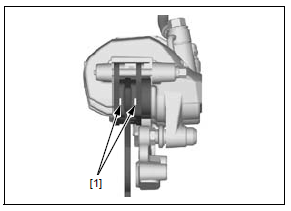
FRONT BRAKE PADS
Check the brake pads for wear.
Always replace the brake pads as a set to assure even disc pressure.
Replace the brake pads if either pad is worn to the wear limit groove [1].
For brake pad removal/installation.
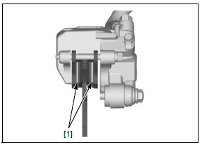
REAR BRAKE PADS
Check the brake pads for wear.
Always replace the brake pads as a set to assure even disc pressure.
Replace the brake pads if either pad is worn to the wear limit groove [1].
For brake pad removal/installation.
BRAKE SYSTEM
INSPECTION
Firmly apply the brake lever or pedal, and check that no air has entered the system.
If the lever or pedal feels soft or spongy when operated, bleed the air from the system.
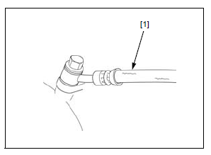
Inspect the brake hoses [1], pipes and fittings for deterioration, cracks, damage and signs of leakage.
Tighten any loose fittings.
Replace hoses, pipes and fittings as required.
BRAKE LIGHT SWITCH
NOTE:
- The brake light switch on the front brake master cylinder cannot be adjusted. If the front brake light switch actuation and brake engagement are not synchronized, either replace the switch unit or the malfunctioning parts of the system.
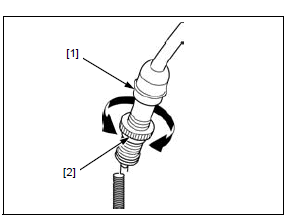
Check that the brake light comes on just prior to the brake actually being engaged.
If the light fails to come on, adjust the switch so that the light comes on at the proper time.
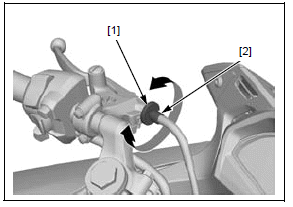
Do not turn the switch body
Hold the switch body [1] and turn the adjuster [2].
HEADLIGHT AIM
NOTE:
- Adjust the headlight aim as specified by local laws and regulations.
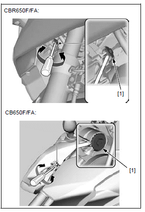
Support the motorcycle in an upright position on a level surface.
Adjust the headlight aim vertically by turning the pinion [1].
A counterclockwise rotation moves the beam up and clockwise rotation moves the beam down.
CLUTCH SYSTEM
Inspect the clutch cable for kinks or damage, and lubricate the cable if necessary.
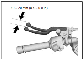
Measure the clutch lever freeplay at the end of the clutch lever.
FREEPLAY: 10 - 20 mm (0.4 - 0.8 in)
The adjuster may be damaged if it is positioned too far out, leaving minimal thread engagement.
Minor adjustment is made with the upper adjuster at the clutch lever.
Loosen the lock nut [1] and turn the adjuster [2] as required.
Tighten the lock nut while holding the adjuster.
If the adjuster is threaded out near its limit and the correct freeplay cannot be obtained, turn the adjuster all the way in and back out one turn, then perform the adjustment at major adjuster as follows.
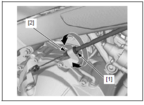
Major adjustment is made with the lower adjusting nut [1] at the clutch lifter arm.
Loosen the lock nut [2] and turn the adjusting nut as required.
Tighten the lock nut while holding the adjusting nut.
If the proper freeplay cannot be obtained, or the clutch slips during test-ride, disassemble and inspect the clutch.
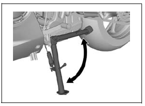
SIDESTAND
Support the motorcycle using a safety stand or hoist.
Check the sidestand spring for damage or loss of tension.
Check the sidestand for movement and lubricate the sidestand pivot if necessary.
For sidestand removal/installation.
Check the sidestand ignition cut-off system:
1. Sit astride the motorcycle and retract the sidestand.
2. Start the engine with the transmission in neutral, then shift the transmission into gear while squeezing the clutch lever.
3. Fully lower the sidestand.
4. The engine should stop as the sidestand is lowered.
If there is a problem with the system, check the sidestand switch.
SUSPENSION
FRONT SUSPENSION INSPECTION
Check the action of the forks by operating the front brake and compressing them several times.
Check the entire fork assembly for signs of leaks, damage or loose fasteners.
Replace damaged components which cannot be repaired.
Tighten all fasteners.
For fork service.
REAR SUSPENSION INSPECTION
Check the action of the shock absorber by compressing them several times.
Check the entire shock absorber assembly for leaks, damage or loose fasteners.
Replace damaged components which cannot be repaired.
Tighten all fasteners.
For shock absorber service.
Support the motorcycle using a hoist or equivalent and raise the rear wheel off the ground.
Check for worn swingarm bearings by grabbing the swingarm ends and attempting to move it side to side.
Replace the bearings if any looseness to noted.
For swingarm service.
REAR SUSPENSION ADJUSTMENT
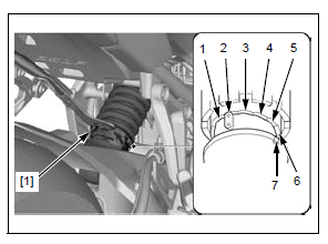
SPRING PRE-LOAD ADJUSTER
Spring pre-load can be adjusted by turning the adjuster [1].
ADJUSTABLE RANGE: 7 positions
Position 1 is for a decrease spring preload (soft), or turn the position 3 to 7 increase spring preload (hard).
The standard position is 2.
NUTS, BOLTS, FASTENERS
Check that all chassis nuts, screws and bolts are tightened to their correct torque value.
Check that all cotter pins, safety clips, hose clamps and cable stays are in place and properly secured.
WHEELS/TIRES
Support the motorcycle using a hoist or equivalent and raise the front wheel off the ground.
Hold the front fork leg and move the front wheel sideways with force to see if the wheel bearings are worn.
For front wheel service.
Support the motorcycle using a hoist or equivalent and raise the rear wheel off the ground.
Hold the swingarm and move the rear wheel sideways with force to see if the wheel and driven flange bearings are worn.
For rear wheel service.
Check the tire pressure with a tire pressure gauge when the tires are cold.
- Front tire
- Rear tire
Check the tires for cuts, embedded nails, or other damage.
Check the front and rear wheels for trueness.
Measure the tread depth at the center of the tires.
Replace the tires when the tread depth reaches the service limits.
- Front tire
- Rear tire
STEERING HEAD BEARINGS
Support the motorcycle using a hoist or equivalent and raise the front wheel off the ground.
Check that the handlebar moves freely from side to side. Make sure the control cables do not interfere with the handlebar rotation.
Check for steering stem bearings by grabbing the fork legs and attempting to move the front fork forward to backward.
If the handlebar moves unevenly, binds, or has vertical movement, inspect the steering bearings.
See also:
 Honda CBR650 - Service manual > Radiator coolant
Check the coolant level of the reserve tank with the engine running at normal operating temperature. The level should be between the "UPPER" [1] and "LOWER" [2] level lines with the motorcycle in an upright position on a level surface.
 Rider's Manual BMW R 1250 GS GSA
 Owner's Manual Harley-Davidson Sportster XL1200X Forty-Eight
 Owner's Manual Honda CBR650R
 Service manual Honda CBR650
 Owner's Manual Honda PCX125
 Owner's Manual Kawasaki Z1000SX
 Service manual Kawasaki Z1000SX
 Owner's Manual Lexmoto Echo
 Owner's Manual Royal Enfield Interceptor 650
 Service manual Royal Enfield Interceptor 650
 Owner's Manual Yamaha MT-07