 Honda CBR650 - Service manual > Radiator coolant
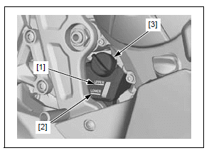
Check the coolant level of the reserve tank with the engine running at normal operating temperature.
The level should be between the "UPPER" [1] and "LOWER" [2] level lines with the motorcycle in an upright position on a level surface.
If the level is low, fill as follows.
Remove the reserve tank cap [3] and fill the tank to the "UPPER" level line with a 1:1 mixture of distilled water and antifreeze.
RECOMMENDED ANTIFREEZE:
EXCEPT TH MODEL:
High quality ethylene glycol antifreeze containing silicate-free
corrosion inhibitors (Mix the distilled water and antifreeze in the ratio of
1:1)
TH MODEL:
HONDA PRE-MIX COOLANT or equivalent
Check to see if there are any coolant leaks when the coolant level decreases very rapidly.
If the reserve tank becomes completely empty, there is a possibility of air getting into the cooling system.
Be sure to remove any air from the cooling system.
Install the reserve tank cap.
COOLING SYSTEM
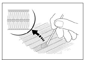
Check the radiator air passages for clogging or damage.
Straighten bent fins with a small flat blade screwdriver and remove insects, mud or other obstructions with compressed air or low water pressure.
Replace the radiator if the air flow is restricted over more than 20% of the radiating surface.
Remove the following:
- Middle cowls (CBR650F/FA)
- Tank shroud B (CB650F/FA)
Check for any coolant leakage from the water hoses and hose joints.
Check the water hoses for cracks or deterioration and replace them if necessary.
Check that all hose clamps are tight.
Install the removed parts in the reverse order of removal.
SECONDARY AIR SUPPLY SYSTEM
Remove the air cleaner housing.
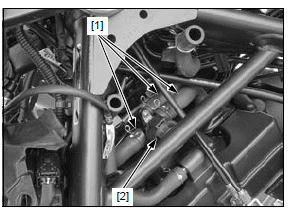
Check the air supply hoses [1] between the air cleaner housing, PAIR control solenoid valve [2] and cylinder head cover for deterioration, damage or loose connections.
Also, check that the hoses are not kinked or pinched.
If the air supply hose show any signs of heat damage, inspect the PAIR check valves.
For secondary air supply system inspection.
EVAPORATIVE EMISSION CONTROL SYSTEM (TH model only)
Open the fuel fill cap.
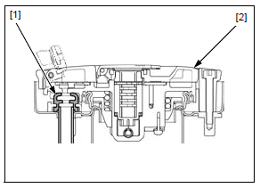
Check the breather seal [1] in the fuel fill cap [2] for deterioration, cracks or damage. Replace it if necessary.
NOTE:
- Always replace the breather seal with a new one when the fuel fill cap is removed for service.
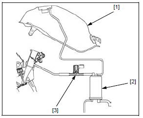
Check the hoses between the fuel tank [1], EVAP canister [2], EVAP purge control solenoid valve [3] for deterioration, damage or loose connection.
Check the EVAP canister for cracks or other damage.
DRIVE CHAIN
DRIVE CHAIN SLACK INSPECTION
Never inspect and adjust the drive chain while the engine is running.
Turn the ignition switch OFF.
Place the motorcycle on its sidestand and shift the transmission into neutral.
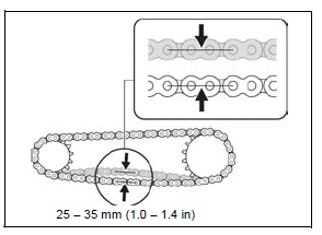
Check the slack in the drive chain lower run midway between the sprockets.
DRIVE CHAIN SLACK: 25 - 35 mm (1.0 - 1.4 in)
NOTICE
Excessive chain slack, 50 mm (2.0 in) or more, may damage the frame.
ADJUSTMENT
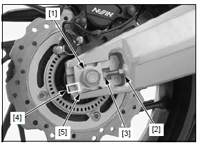
Loosen the rear axle nut [1] and adjuster lock nuts [2].
Turn the adjusting bolts [3] an equal number of a turn until the correct drive chain slack is obtained.
Make sure the scales [4] on both swingarm end are aligned with the end face of the adjusting plates [5].
Tighten the axle nut to the specified torque.
TORQUE: 98 N*m (10.0 kgf*m, 72 lbf*ft)
Tighten each lock nut while holding the adjusting bolt to the specified torque.
TORQUE: 27 N*m (2.8 kgf*m, 20 lbf*ft)
Recheck the drive chain slack and free wheel rotation.
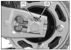
Check the drive chain wear indicator label attached on the left swingarm.
If the index notch [1] of the left adjusting plate reaches the red zone [2] of the wear indicator label, replace the drive chain with a new one.
CLEANING AND LUBRICATION
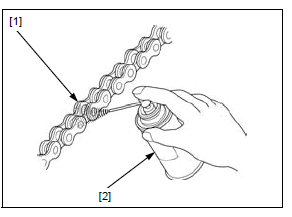
Clean the drive chain [1] with a chain cleaner designed specifically for O-ring chains or a neutral detergent. Use a soft brush if the drive chain is dirty.
NOTICE
Do not use a steam cleaner, high pressure cleaner, wire brush, volatile solvent such as gasoline and benzene, abrasive cleaner or a chain cleaner NOT designed specifically for O-ring chains to clean the drive chain.
Inspect the drive chain for possible damage or wear.
Replace any drive chain that has damaged rollers, loose fitting links, or otherwise appears unserviceable.
Be sure the drive chain has dried completely before lubricating.
Lubricate the drive chain with drive chain lubricant [2] designed specifically for O-ring chains or SAE #80 - 90 gear oil.
NOTICE
Do not use a chain lubricant NOT designed specifically for use with O-ring chains to lubricate the drive chain.
Wipe off the excess oil or drive chain lubricant.
SPROCKET INSPECTION
Remove the drive sprocket cover.
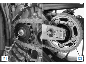
Inspect the drive and driven sprocket teeth for wear or damage, replace if necessary.
Never use a new drive chain on worn sprockets.
Both chain and sprockets must be in good condition, or new replacement chain will wear rapidly.
Check the attaching bolt and nuts on the drive and driven sprockets.
If any are loose, torque them to the specified toque.
TORQUE:
- Drive sprocket bolt: 54 N*m (5.5 kgf*m, 40 lbf*ft)
- Driven sprocket nut: 108 N*m (11.0 kgf*m, 80 lbf*ft)
Install the drive sprocket cover.
REPLACEMENT
This motorcycle uses a drive chain with a staked master link.
Fully slacken the drive chain.
Remove the drive chain using the special tool.
TOOL: Drive chain tool set 07HMH-MR10103
NOTE:
- When using the special tool, follow the manufacturer's instruction.
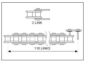
Remove the excess drive chain links from a new drive chain with the drive chain tool set.
SPECIFIED LINKS: 118 LINKS
REPLACEMENT CHAIN:
DID525V11-118LE
RK525KRW-118LE
Never reuse the old drive chain, master link, master link plate and O-rings.
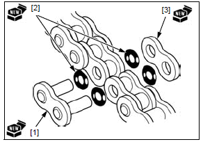
Insert a new master link [1] with new O-rings [2] from the inside of the drive chain, and install a new plate [3] and O-rings with the identification mark facing out.
Assemble the master link, O-rings and plate.
TOOL: Drive chain tool set 07HMH-MR10103
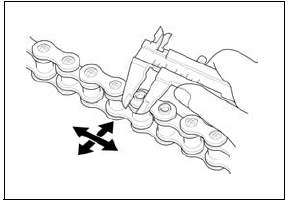
Make sure that the master link pins [1] are installed properly.
Measure the master link pin length projected from the plate.
STANDARD LENGTH: Approx. 1.3 mm (0.05 in)
Stake the master link pins with the drive chain tool set.

Make sure the pins are staked properly by measuring the diameter of the staked area.
DIAMETER OF STAKED AREA:
DID525V11: 5.50 - 5.80 mm (0.217 - 0.228 in)
RK525KRW: 5.30 - 5.70 mm (0.209 - 0.224 in)
After staking, check the staked area of the master link for cracks.
If there is any cracking, replace the master link, O-rings and plate.
See also:
 Honda CBR650 - Service manual > Air cleaner
NOTE: The viscous paper element type air cleaner cannot be cleaned because the element contains a dust adhesive. If the motorcycle is used in unusually wet or dusty areas, more frequent inspections are required.
Honda CBR650 - Service manual > Drive chain slider
Check the drive chain slider [1] for wear or damage. The drive chain slider must be replaced if it is worn to the wear limit lines [2].
 Rider's Manual BMW R 1250 GS GSA
 Owner's Manual Harley-Davidson Sportster XL1200X Forty-Eight
 Owner's Manual Honda CBR650R
 Service manual Honda CBR650
 Owner's Manual Honda PCX125
 Owner's Manual Kawasaki Z1000SX
 Service manual Kawasaki Z1000SX
 Owner's Manual Lexmoto Echo
 Owner's Manual Royal Enfield Interceptor 650
 Service manual Royal Enfield Interceptor 650
 Owner's Manual Yamaha MT-07