 Honda CBR650 - Service manual > Air cleaner
NOTE:
- The viscous paper element type air cleaner cannot be cleaned because the element contains a dust adhesive.
- If the motorcycle is used in unusually wet or dusty areas, more frequent inspections are required.
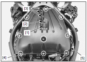
Lift the fuel tank and support it.
Disconnect the IAT sensor 2P (Black) connector [1] and release the wire [2] from the wire guides [3] Remove the tapping screws [4] and air cleaner lid [5].
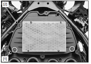
Remove the two tapping screws [1] and air cleaner element [2].
Replace the air cleaner element in accordance with the maintenance schedule or any time it is excessively dirt or damaged.
Clean the inside of the air cleaner lid and housing.
Make sure the rubber seals in the housing and lid is in position and in good condition.
Installation is in the reverse order of removal.
TORQUE:
Air cleaner element tapping screw:
1.1 N*m (0.1 kgf*m, 0.8 lbf*ft)
Air cleaner lid tapping screw:
1.1 N*m (0.1 kgf*m, 0.8 lbf*ft)
SPARK PLUG
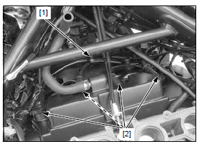
Remove the PAIR control solenoid valve assembly.
Release the wire guide [1] and disconnect the spark plug caps [2].
Clean around the spark plug base with compressed air before removing the plug, and be sure that no debris is allowed to enter into the combustion chamber.
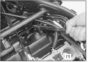
Remove the spark plug [1].
Check the insulator for cracks or damage, and the electrodes for wear, fouling or discoloration. Replace the plug if necessary.
SPECIFIED SPARK PLUG:
CR9EH-9 (NGK)
U27FER9 (DENSO)
Clean the spark plug electrodes with a wire brush or special plug cleaner.
Check the gap between the center and side electrodes with a wire-type feeler gauge.
SPARK PLUG GAP: 0.80 - 0.90 mm (0.031 - 0.035 in)
If necessary, adjust the gap by bending the side electrode carefully.
Install and hand tighten the spark plug to the cylinder head, then tighten the spark plug to the specified torque.
TORQUE: 16 N*m (1.6 kgf*m, 12 lbf*ft)
Install the PAIR control solenoid valve assembly.
VALVE CLEARANCE
INSPECTION
NOTE:
- Inspect and adjust the valve clearance while the engine is cold (below 35ºC/95ºF).
Remove the following:
- Cylinder head cover
- Timing hole cap and O-ring
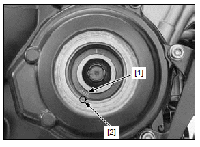
Rotate the crankshaft clockwise slowly and align the "T" mark [1] with the index notch [2] in the crankcase cover.
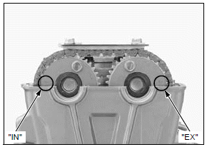
Make sure the timing marks ("IN" and "EX") on the sprockets are flush with the cylinder head surface and facing outward as shown.
If the marks are not this position, turn the crankshaft clockwise one full turn (360º) and realign the "T" mark with the index notch.
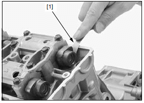
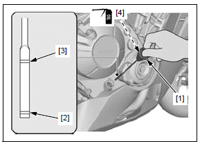
Insert the feeler gauge [1] between the valve lifter and the cam lobe.
Record the clearance for each valve for reference in shim selection if adjustment is required.
Check the valve clearance for the No.1 and No.3 cylinder intake valves using a feeler gauge.
VALVE CLEARANCE:
IN: 0.20 +- 0.03 mm (0.008 +- 0.001 in)
Turn the crankshaft clockwise 1/2 turn (180º), align the index line [1] on the CKP sensor rotor so that it is facing down as shown.
Record the clearance for each valve for reference in shim selection if adjustment is required.
Check the valve clearance for the No.2 and No.4 cylinder exhaust valves using a feeler gauge.
VALVE CLEARANCE:
EX: 0.28 +- 0.03 mm (0.011 +- 0.001 in)
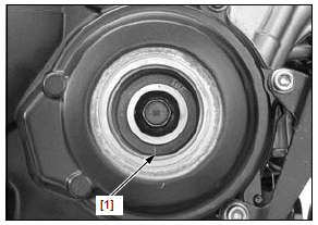
Turn the crankshaft clockwise 1/2 turn (180º), align the "T" mark on the CKP sensor rotor with the index mark on the right crankcase cover.
Record the clearance for each valve for reference in shim selection if adjustment is required.
Check the valve clearance for the No.2 and No.4 cylinder intake valves using feeler gauge.
VALVE CLEARANCE:
IN: 0.20 +- 0.03 mm (0.008 +- 0.001 in)
Turn the crankshaft clockwise 1/2 turn (180º), align the index line on the CKP sensor rotor so that it is facing down as shown.
Record the clearance for each valve for reference in shim selection if adjustment is required.
Check the valve clearance for the No.1 and No.3 cylinder exhaust valves using a feeler gauge.
VALVE CLEARANCE:
EX: 0.28 +- 0.03 mm (0.011 +- 0.001 in)
ADJUSTMENT
It is not necessary to remove the cam sprocket from the camshaft except when replacing the camshaft and/or cam sprocket.
Remove the camshafts.
Remove the valve lifters [1] and shims [2].
- Shim may stick to the inside of the valve lifter. Do not allow the shims to fall into the crankcase.
- Mark all valve lifters and shims to ensure correct reassembly in their original locations.
- The valve lifter can be easily removed with a valve lapping tool or magnet.
- The shims can be easily removed with a tweezers or magnet.
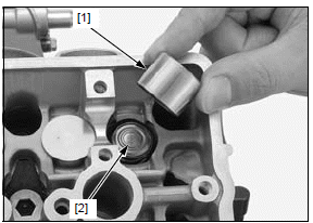
Clean the valve shim contact area in the valve lifter [1] with compressed air.
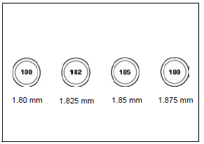
Sixty-nine different thickness shims are available from the thinnest 1.200 mm thickness shim to the thickest 2.900 mm thickness shim in intervals of 0.025 mm.
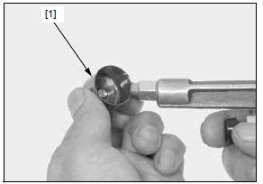
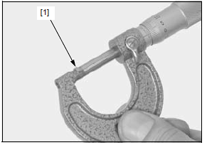
Measure the shim [1] thickness and record it.
Calculate the new shim thickness using the equation below.
A = (B - C) + D
- New shim thickness
- Recorded valve clearance
- Specified valve clearance
- Old shim thickness
- Make sure of the correct shim thickness by measuring the shim by micrometer.
- Reface the valve seat if carbon deposit result in a calculated dimension of over 2.900 mm.
Install the shims and valve lifters in their original locations
Install the newly selected shim [1] on the valve retainer.
Apply molybdenum disulfide oil to the valve lifter [2] sliding surface.
Install the valve lifters into the valve lifter holes.
Install the camshaft.
Rotate the camshafts by rotating the crankshaft clockwise several times.
Recheck the valve clearance.
Check that the O-ring is in good condition, replace if necessary.
Apply engine oil to the timing hole cap O-ring.
Apply grease to the timing hole cap threads.
Install and tighten the timing hole cap to the specified torque.
TORQUE:18 N*m (1.8 kgf*m, 13 lbf*ft)
Install the removed parts in the reverse order of removal.
ENGINE OIL/OIL FILTER
OIL LEVEL CHECK
Hold the motorcycle in an upright position.
Start the engine and let it idle for 3 - 5 minutes.
Stop the engine and wait 2 - 3 minutes.
Remove the oil filler cap/dipstick [1] and wipe it clean.
Reinstall the oil filler cap/dipstick, but do not screw it.
Remove the oil filler cap/dipstick and check the oil level.
If the level is below or near the lower level [2] on the dipstick, fill the recommended engine oil to the upper level [3].
RECOMMENDED ENGINE OIL:
Honda "4-stroke motorcycle oil" or an equivalent API classification: SG or
higher (except oils labeled as energy conserving on the circular API service
label)
Viscosity: SAE 10W-30
JASO T 903 standard: MA
Check that the O-ring [4] is in good condition, replace it if necessary.
Apply engine oil to the O-ring.
Install the oil filler cap/dipstick.
ENGINE OIL & FILTER CHANGE
Warm up the engine.
Stop the engine and remove the oil filler cap/dipstick.
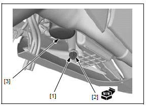
Remove the oil drain bolt [1] and sealing washer [2] to drain the engine oil.
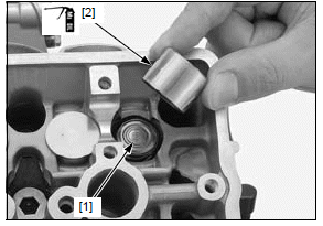
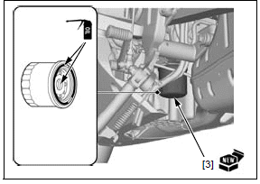
Remove the oil filter cartridge [3] using the special tool.
TOOL: Oil filter wrench 07HAA-PJ70101
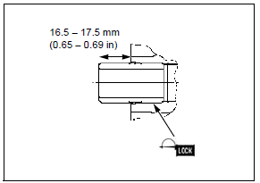
Check that the oil filter boss protrusion from the crankcase is specified length as shown.
SPECIFIED LENGTH: 16.5 - 17.5 mm (0.65 - 0.69 in)
NOTE:
- If the oil filter boss is removed, apply locking agent to the oil filter boss threads and install it.
Apply engine oil to the threads and O-ring of a new oil filter cartridge [1].
Install the oil filter cartridge and tighten it to the specified torque.
TOOL: Oil filter wrench 07HAA-PJ70101
TORQUE: 26 N*m (2.7 kgf*m, 19 lbf*ft)
Install a new sealing washer onto the drain bolt.
Install and tighten the drain bolt/sealing washer to the specified torque.
TORQUE:30 N*m (3.1 kgf*m, 22 lbf*ft)
Fill the crankcase with the recommended engine oil.
ENGINE OIL CAPACITY:
2.6 liters (2.7 US qt, 2.3 Imp qt) at draining
2.9 liters (3.1 US qt, 2.6 Imp qt) at oil filter change
3.5 liters (3.7 US qt, 3.1 Imp qt) at disassembly
Check the oil level.
Make sure there are no oil leaks.
ENGINE IDLE SPEED
NOTE:
- Inspect the idle speed after all other engine maintenance items have been performed and are within specifications.
- Before checking the idle speed, inspect the following items:
- No MIL blinking
- Throttle operation and throttle grip freeplay
- The engine must be warm for accurate idle speed inspection.
- This system eliminates the need for manual idle speed adjustment.
Start the engine, warm it up to normal operation temperature and let it idle.
Check the idle speed.
IDLE SPEED: 1,250 +- 100 min-1 (rpm)
If the idle speed is out of the specification, check the following:
- Air cleaner element condition
- Throttle operation and throttle grip freeplay
- Spark plug condition
- Intake air leak or engine top-end problem
- IACV operation
See also:
 Honda CBR650 - Service manual > Maintenance schedule
SERVICE INFORMATION GENERAL Place the motorcycle on a level surface before starting any work. Maintenance schedule
Honda CBR650 - Service manual > Radiator coolant
Check the coolant level of the reserve tank with the engine running at normal operating temperature. The level should be between the "UPPER" [1] and "LOWER" [2] level lines with the motorcycle in an upright position on a level surface.
 Rider's Manual BMW R 1250 GS GSA
 Owner's Manual Harley-Davidson Sportster XL1200X Forty-Eight
 Owner's Manual Honda CBR650R
 Service manual Honda CBR650
 Owner's Manual Honda PCX125
 Owner's Manual Kawasaki Z1000SX
 Service manual Kawasaki Z1000SX
 Owner's Manual Lexmoto Echo
 Owner's Manual Royal Enfield Interceptor 650
 Service manual Royal Enfield Interceptor 650
 Owner's Manual Yamaha MT-07