 Kawasaki Z1000SX - Service manual > ECU
ECU Identification
- Most countries have their own regulations, so each ECU has different characteristic. So, do not confuse ECU with each other and use only the ECU for your model. Otherwise, the motorcycle cannot clear the regulation.
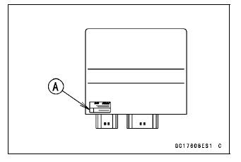
ECU Identification
Full: Full Power
H: Honeycomb Type Catalyst
78.2: Maximum Horsepower 78.2 kW (106.3 PS)
ECU Removal
NOTICE Never drop the ECU especially on a hard surface.
Such a shock to the ECU can damage it.
NOTE
- Refer to the Immobilizer System Parts Replacement in the Electrical System chapter for the immobilizer models (see Immobilizer System Parts Replacement in the Electrical System chapter).
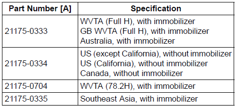
- Remove:
Relay Box (see Relay Box Removal in the Electrical System chapter)
ECU Connectors [A]
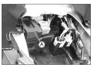
ECU [B]
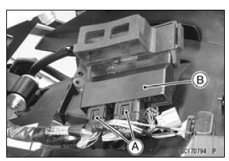
ECU Installation
- Connect the ECU connectors [A].
- Install the ECU [B] into the rubber protector [C].
- Insert the slits of the rubber protector to the projections [D] of the bracket.
ECU Power Supply Inspection
- Visually inspect the ECU connectors.
If the connector is clogged with mud or dust, blow it off with compressed air.
- Remove the ECU (see ECU Removal).
- Visually inspect the terminals [A] of the ECU connectors.
If the terminals of the main harness connectors are damaged, replace the main harness.
If the terminals of the ECU connectors are damaged, replace the ECU.
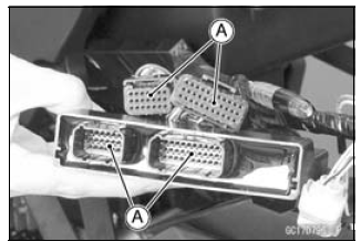
- Turn the ignition switch OFF.
- Disconnect the ECU connectors [A].
- Set the hand tester [B] to the × 1 Ω range and check the following wiring for continuity.
Special Tool - Hand Tester: 57001-1394
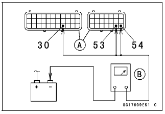
ECU Grounding Inspection
Connections:
(I) BK/Y leads (ECU terminal 30, 53 or 54) ←→ Battery (-) Terminal
(II) Engine Ground ←→ Battery (-) Terminal
Criteria:
Both: 0 Ω
If no continuity, check the connectors, the engine ground lead, or main harness, and repair or replace them if necessary.
If the wiring is good, check the power source voltage of the ECU.
NOTE
- Be sure the battery is fully charged.
- Connect the ECU and relay box connectors.
- Connect a digital meter [A] to the connectors [B] with the needle adapter set.
Special Tool - Needle Adapter Set: 57001-1457
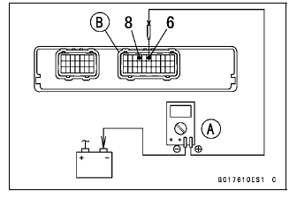
ECU Power Supply Inspection
Connections:
(I)
Digital Meter (+) → Terminal 6 (BR/W)
Digital Meter (-) → Battery (-) terminal
(II)
Digital Meter (+) → Terminal 8 (W/BK)
Digital Meter (-) → Battery (-) terminal
Ignition Switch OFF:
Terminal 6 (BR/W): 0 V
Terminal 8 (W/BK): Battery Voltage
Ignition Switch ON:
Both: Battery Voltage
If the reading is out of the specification, check the following.
Main Fuse 30 A (see Fuse Inspection in the Electrical System chapter)
FI Fuse 15 A (see Fuse Inspection Electrical System chapter)
ECU Main Relay (see Relay Circuit Inspection in the Electrical System chapter)
Power Source Wiring (see wiring diagram in this section)If the fuse, wiring and relay are good, replace the ECU (see ECU Removal/Installation).
ECU Power Source Circuit
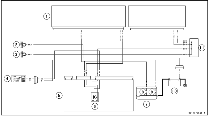
- ECU
- Meter Ground
- Frame Ground
- Ignition Switch
- Relay Box
- ECU Main Relay
- Starter Relay
- FI Fuse 15 A
- Main Fuse 30 A
- Battery 12 V 8 Ah
- Water-proof Joint C
DFI Power Source
ECU Fuse Removal
- Refer to the 15 A FI Fuse Removal in the Electrical System chapter.
ECU Fuse Installation
If a fuse fails during operation, inspect the DFI system to determine the cause, and then replace it with a new fuse of proper amperage.
- Refer to the Fuse Installation in the Electrical System chapter.
ECU Fuse Inspection
- Refer to the Fuse Inspection in the Electrical System chapter.
ECU Main Relay Removal/Installation
- The ECU main relay is built in the relay box [A].
- Refer to the Relay Box Removal in the Electrical System chapter.
ECU Main Relay Inspection
- Refer to the Relay Circuit Inspection in the Electrical System chapter.
See also:
 Kawasaki Z1000SX - Service manual > Oxygen Sensor - Incorrect Output Voltage (Service Code 94, Equipped Models)
Oxygen Sensor Removal/Installation Refer to the Oxygen Sensor Removal/Installation in the Electrical System chapter. Oxygen Sensor Inspection Warm up the engine thoroughly until the radiator fan starts. Turn the ignition switch OFF. Remove the right lower fairing (see Lower Fairing Removal in the Frame chapter). Open the clamp [A], and pull out the oxygen sensor lead connector [B]. Disconnect the oxygen sensor lead connector (4 pins connector) and connect the harness adapter [A] between these connectors.
Kawasaki Z1000SX - Service manual > Fuel Line
Fuel Pressure Inspection NOTE Be sure the battery is fully charged. Remove: Fuel Hose (see Fuel Hose Replacement in the Periodic Maintenance chapter) Support the fuel tank with a suitable bar (see Fuel Tank Removal in the Fuel System (DFI) chapter). Be sure to place a piece of cloth around the fuel outlet pipe of the fuel pump and the delivery pipe of the throttle body assy.
 Rider's Manual BMW R 1250 GS GSA
 Owner's Manual Harley-Davidson Sportster XL1200X Forty-Eight
 Owner's Manual Honda CBR650R
 Service manual Honda CBR650
 Owner's Manual Honda PCX125
 Owner's Manual Kawasaki Z1000SX
 Service manual Kawasaki Z1000SX
 Owner's Manual Lexmoto Echo
 Owner's Manual Royal Enfield Interceptor 650
 Service manual Royal Enfield Interceptor 650
 Owner's Manual Yamaha MT-07