 Kawasaki Z1000SX - Service manual > Oxygen Sensor - Incorrect Output Voltage (Service Code 94, Equipped Models)
Oxygen Sensor Removal/Installation
- Refer to the Oxygen Sensor Removal/Installation in the Electrical System chapter.
Oxygen Sensor Inspection
- Warm up the engine thoroughly until the radiator fan starts.
- Turn the ignition switch OFF.
- Remove the right lower fairing (see Lower Fairing Removal in the Frame chapter).
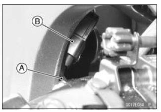
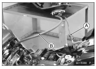
- Open the clamp [A], and pull out the oxygen sensor lead connector [B].
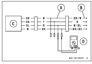
- Disconnect the oxygen sensor lead connector (4 pins connector) and
connect the harness adapter [A] between these connectors.
[B] Main Harness
[C] Oxygen Sensor
Special Tool - Measuring Adapter: 57001-1700
- Connect a digital meter [D] to the harness adapter leads.
Oxygen Sensor Output Voltage
Connections to Adapter:
Digital Meter (+) → R (sensor BL) lead
Digital Meter (−) → BK (sensor W) lead
- Remove: Air Cleaner Housing (see Air Cleaner Housing Removal)
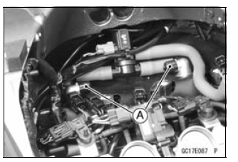
- Disconnect the stick coil connectors [A].
- Separate the air switching valve hoses [B] from the air suction valve
covers.
- Do not disconnect the air switching valve connector [C].
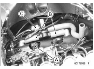
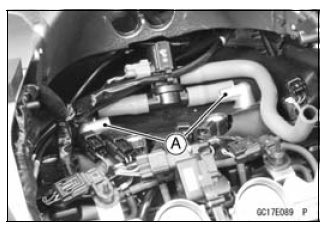
- Install the suitable plugs [A] on the fitting of the air suction valve covers, and shut off the secondary air.
- Connect the stick coil connectors.
- Install the air cleaner housing temporarily (see Air Cleaner Housing Installation).
- Remove the fuel hose (see Fuel Hose Replacement in the Periodic Maintenance chapter).
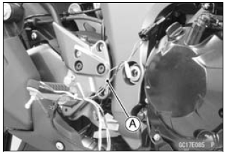
- Connect the following parts temporary.
Fuel Pump Lead Connector [A]
Fuel Hose [B]
Special Tool - Fuel Hose: 57001-1607
- Start the engine, and let it idle.
- Measure the output voltage with the connector joined.
Output Voltage (with Plugs, Rich)
Standard: DC 0.7 V or more
- Next, remove the air cleaner housing to take out the plugs from the fittings [A] of the air suction valve covers.
- Install the air cleaner housing.
- Start the engine, and let it idle.
- Measure the output voltage with the connector joined.
Output Voltage (without Plugs, Lean)
Standard: DC 0.2 V or less
- Turn the ignition switch OFF.
If the reading is out of the standard (with plugs: DC 0.7 V or more, without plugs: DC 0.2 V or less), check the following.
Fuel Pressure (see Fuel Pressure Inspection)
Fuel Injector (see Fuel Injectors section)If the fuel pressure and fuel injectors are good, replace the sensor.
If the reading is within the standard (with plugs: DC 0.7 V or more, without plugs: DC 0.2 V or less), check the ECU for its ground and power supply (see ECU Power Supply Inspection).
If the ground and power supply are good, replace the ECU (see ECU Removal/Installation).
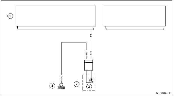
Oxygen Sensor Circuit
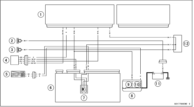
- ECU
- Meter Ground
- Frame Ground
- Oxygen Sensor
- Ignition Switch
- Relay Box
- ECU Main Relay
- Starter Relay
- FI Fuse 15 A
- Main Fuse 30 A
- Battery 12 V 8 Ah
- Water-proof Joint C
Warning Indicator Light (LED)
Light (LED) Inspection
- The warning indicator light (LED) [A] is used for the FI indicator, immobilizer indicator (immobilizer models) and oil pressure warning indicator.
- In this model, the warning indicator light (LED) (FI/immobilizer) blink by the data sent from the ECU.
- Refer to the Meter Unit Inspection in the Electrical System chapter for the warning indicator light (LED) (FI/immobilizer) inspection.

Warning Indicator Light (LED) (FI/Immobilizer) Circuit
- ECU
- Meter Unit
- Warning Indicator Light (LED)
- Meter Ground
See also:
 Kawasaki Z1000SX - Service manual > Oxygen Sensor Heater (Service Code 67, Equipped Models)
Oxygen Sensor Heater Removal/Installation The oxygen sensor heater is built in the oxygen sensor. So, the heater itself can not be removed. Remove the oxygen sensor (see Oxygen Sensor Removal (Equipped Models) in the Electrical System chapter).
Kawasaki Z1000SX - Service manual > ECU
ECU Identification Most countries have their own regulations, so each ECU has different characteristic. So, do not confuse ECU with each other and use only the ECU for your model. Otherwise, the motorcycle cannot clear the regulation.
 Rider's Manual BMW R 1250 GS GSA
 Owner's Manual Harley-Davidson Sportster XL1200X Forty-Eight
 Owner's Manual Honda CBR650R
 Service manual Honda CBR650
 Owner's Manual Honda PCX125
 Owner's Manual Kawasaki Z1000SX
 Service manual Kawasaki Z1000SX
 Owner's Manual Lexmoto Echo
 Owner's Manual Royal Enfield Interceptor 650
 Service manual Royal Enfield Interceptor 650
 Owner's Manual Yamaha MT-07