 Honda CBR650 - Service manual > Engine removal/installation
Service information
GENERAL
- A hoist or equivalent is required to support the motorcycle when removing and installing the engine.
- A floor jack or other adjustable support is required to support and maneuver the engine.
NOTICE
Do not use the oil filter as a jacking point.
- When removing/installing the engine, tape the frame around the engine beforehand for frame protection.
- When installing the engine, be sure to tighten the engine mounting fasteners to the specified torque in the specified sequence. If you mistake the torque or sequence, loosen all mounting fasteners, then tighten them again to the specified torque in the correct sequence.
- The following components can be serviced with the engine installed in
the frame.
- Starter motor
- Throttle body
- Air cleaner housing
- Water pump
- Oil pump
- Oil strainer
- Camshaft
- Cam chain tensioner lifter
- Clutch
- Gearshift linkage
- Stator
- Flywheel
- Starter clutch
- Cylinder head/valves
- The following components require engine removal for service.
- Transmission
- Crankshaft
- Piston/cylinder
Component location
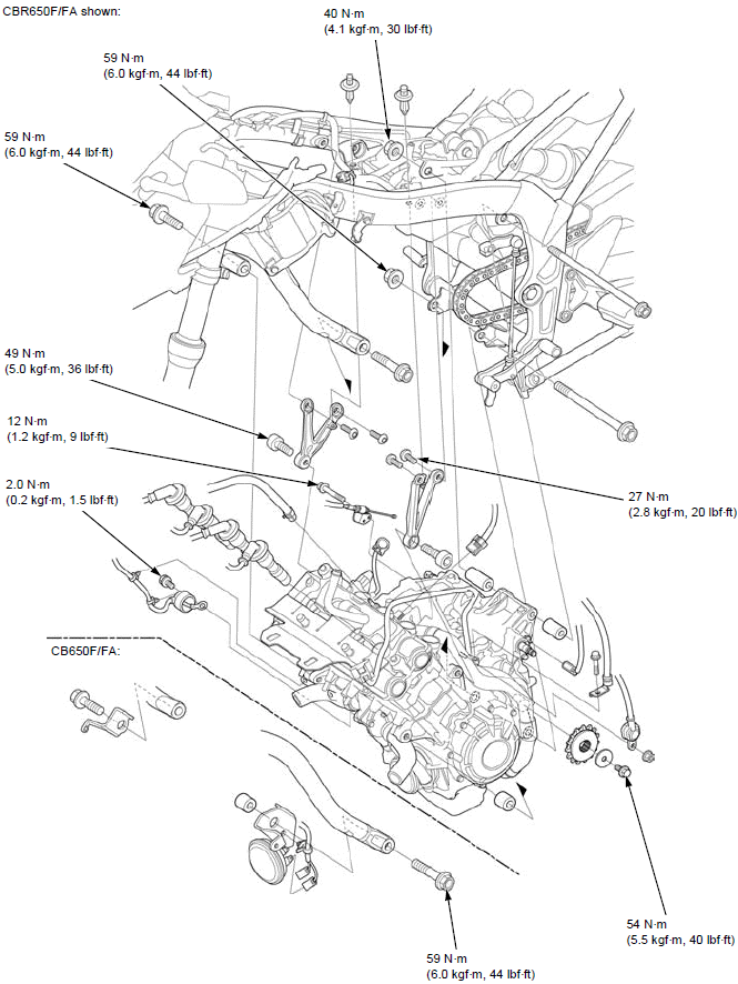
CBR650F/FA shown:
Engine removal
Drain the engine oil.
Drain the coolant.
Fully slacken the drive chain.
Remove the following:
- Drive sprocket cover
- Radiator
- Exhaust pipe/muffler
- Throttle body
- VS sensor
- Radiator reserve tank
- ABS modulator cover
- EVAP canister (TH model only)
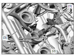
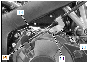
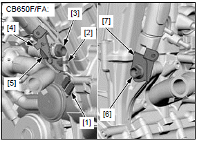
Disconnect the following:
- CKP sensor 2P (Black) connector [1]
- ECT sensor 2P (Blue) connector [2]
- Water bleeding hose [3]
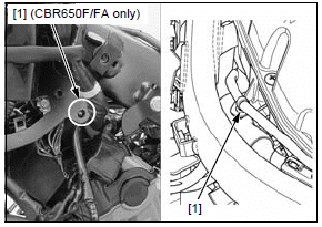
Release the alternator wire clips [1] and remove the wire out of the frame.
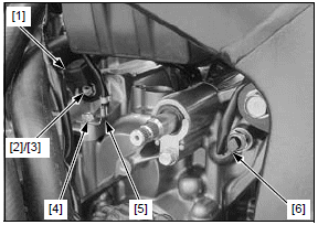
Release the terminal cap [1].
Remove the terminal nut [2] and disconnect the starter motor cable [3].
Remove the starter motor mounting bolt [4] and negative (-) cable [5].
Disconnect the neutral switch connector [6].
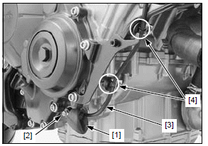
Remove the bolt [1] and clutch cable holder [2], then disconnect the clutch cable [3] from the clutch lifter arm [4].
Release the rubber cap [1] from the EOP switch.
Remove the terminal screw [2] and disconnect the switch wire [3].
Release the wire clips [4].
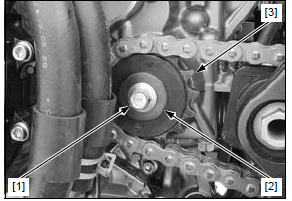
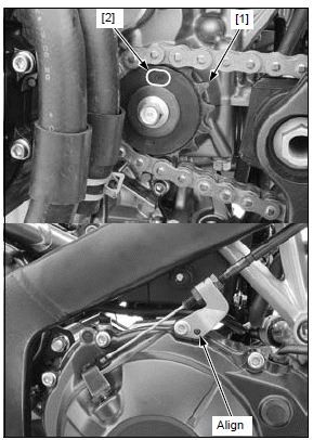
Remove the drive sprocket bolt [1], washer [2] and drive sprocket [3].
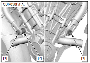
CBR650F/FA:
Support the motorcycle securely with a hoist or equivalent.
Do not use the oil filter as a jacking point.
Place a floor jack or other adjustable support under the engine.
NOTE:
- The jack height must be continually adjusted to relieve stress for ease of bolt removal.
Remove the following:
- Front engine hanger bolts [1]
- Collar [2] (left side only)
CB650F/FA:
Support the motorcycle securely with a hoist or equivalent.
Do not use the oil filter as a jacking point.
Place a floor jack or other adjustable support under the engine.
NOTE:
- The jack height must be continually adjusted to relieve stress for ease of bolt removal.
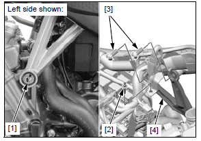
Disconnect the horn wire connectors [1] and release the wire clip [2].
Remove the following:
- Left front engine hanger bolt [3]
- Left tank shroud stay assembly [4]
- Collar [5]
- Right front engine hanger bolt [6]
- Right tank shroud stay [7]
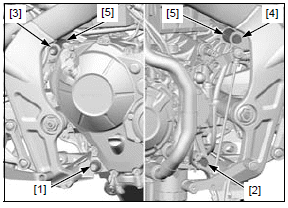
Remove the following:
- Upper engine hanger bolts [1]
- Clips [2]
- Engine hanger bracket bolts [3]
- Both engine hangers [4]
Remove the rear lower engine hanger nut [1] and bolt [2].
Remove the rear upper engine hanger nut [3], bolt [4] and collars [5].
During engine removal, hold the engine securely and be careful not to damage the frame and engine.
Carefully lower the jack or adjustable support, then remove the engine from the frame.
Engine installation
During engine installation, hold the engine securely and be careful not to damage the frame and engine.
Place the engine in the frame, then loosely install all the bolts, collars and nuts.
NOTE:
- Place the jack or other adjustable support under the engine.
- Do not use the oil filter as a jacking point.
- The jack height must be continually adjusted to relieve stress for ease bolt installation.
- Carefully align the mounting points with the jack to prevent damage to engine, frame, radiator hoses, wires and cables.
Tighten the bolts and nuts to the specified torque in the specified sequence as shown.
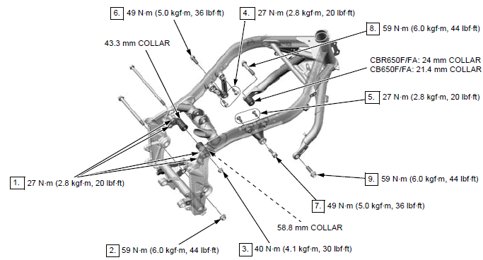
Install the removed parts in the reverse order of removal.
TORQUE:
Drive sprocket bolt:
54 N*m (5.5 kgf*m, 40 lbf*ft)
EOP switch terminal screw:
2.0 N*m (0.2 kgf*m, 1.5 lbf*ft)
Right crankcase cover bolt:
12 N*m (1.2 kgf*m, 9 lbf*ft)
NOTE:
- Install the drive sprocket [1] with its "OUT" mark [2] facing out.
- Align the clutch cable holder hole with the right crankcase cover boss.
Adjust the following:
- Throttle grip freeplay
- Clutch lever freeplay
- Drive chain slack
Fill the engine with the recommended engine oil.
Fill and bleed the cooling system.
Check the exhaust system and cooling system for leaks.
See also:
 Honda CBR650 - Service manual > Piston/cylinder
PISTON/CONNECTING ROD REMOVAL NOTICE Before piston removal, place a clean shop towel around the connecting rod to prevent damaging the cylinder sleeve. Do not try to remove the piston/connecting rod assembly from bottom of the cylinder; the assembly will get stuck in the gap between the cylinder liner and the upper crankcase. Do not interchange the bearing inserts. They must be installed in their original locations or the correct bearing oil clearance may not be obtained, resulting in engine damage.
 Rider's Manual BMW R 1250 GS GSA
 Owner's Manual Harley-Davidson Sportster XL1200X Forty-Eight
 Owner's Manual Honda CBR650R
 Service manual Honda CBR650
 Owner's Manual Honda PCX125
 Owner's Manual Kawasaki Z1000SX
 Service manual Kawasaki Z1000SX
 Owner's Manual Lexmoto Echo
 Owner's Manual Royal Enfield Interceptor 650
 Service manual Royal Enfield Interceptor 650
 Owner's Manual Yamaha MT-07