 Kawasaki Z1000SX - Service manual > Engine Removal/Installation
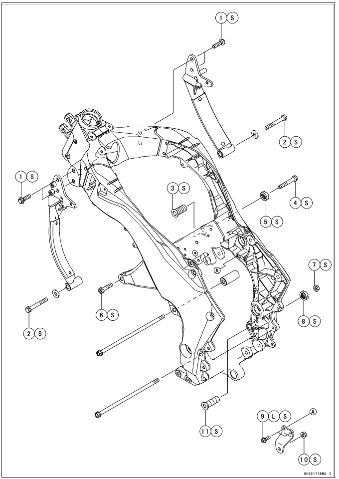
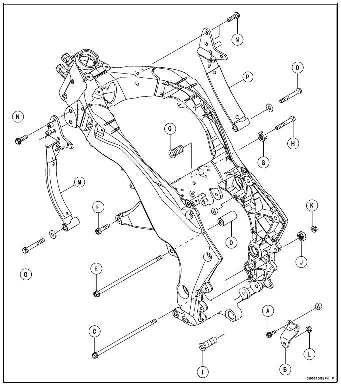
Exploded View
L: Apply a non-permanent locking agent.
S: Follow the specified tightening sequence.
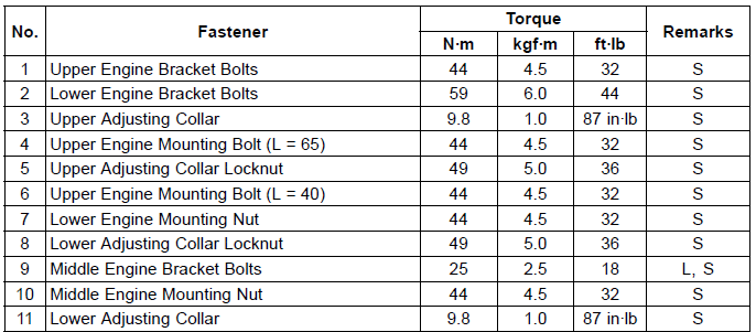
Special Tool
Engine Mount Nut Wrench: 57001-1450
Engine Removal/Installation
Engine Removal
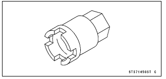
- Support the rear part of the swingarm with a stand.
- Squeeze the brake lever slowly and hold it with a band [A].
WARNING Motorcycle may fall over unexpectedly resulting in an accident or injury. Be sure to hold the front brake when removing the engine.
NOTICE Be sure to hold the front brake when removing the engine, or the motorcycle may fall over. The engine or the motorcycle could be damaged.
- Remove:
Engine Oil (Drain, see Engine Oil Change in the Periodic Maintenance chapter)
Coolant (Drain, see Coolant Change in the Periodic Maintenance chapter)
Lower Fairing (see Lower Fairing Removal in the Frame chapter)
Clutch Cable Lower End (see Clutch Cable Removal in the Clutch chapter)
Radiator (see Radiator and Radiator Fan Removal in the Cooling System chapter)
Exhaust Pipe (see Exhaust Pipe Removal in the Engine Top End chapter)
Air Switching Valve (see Air Switching Valve Removal in the Engine Top End chapter)
Throttle Body Assy (see Throttle Body Assy Removal in the Fuel System (DFI) chapter)
Shift Lever (see Shift Pedal Removal in the Crankshaft/ Transmission chapter)
Engine Sprocket (see Engine Sprocket Removal in the Final Drive chapter) - Remove:
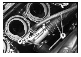
Clamps [A]
Water Hoses [B]
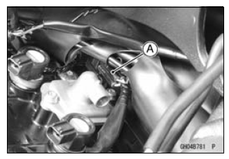
- Remove the connector [A] from the bracket on the air suction valve cover.
- Disconnect the connector.
- Disconnect:
Starter Motor Cable (see Starter Motor Removal in the Electrical System chapter)
Alternator Lead Connector (see Alternator Cover Removal in the Electrical System chapter)
Crankshaft Sensor Lead Connector (see Crankshaft Sensor Removal in the Electrical System chapter)
- Remove:
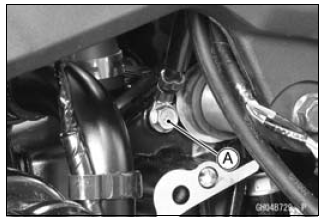
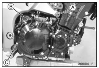
Engine Ground Cable Terminal Bolt [A]
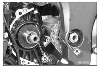
- Remove the drive chain [A] from the output shaft [B].
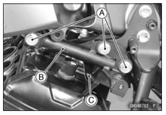
- Remove: (Both Sides)
Bolts [A]
Brackets [B]
Quick Rivets [C]
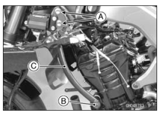
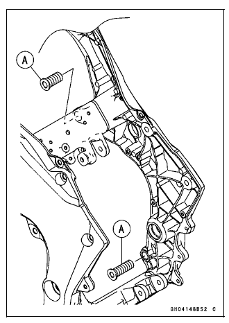
- Remove: (Left Side)
Upper Engine Bracket Bolts [A]
Lower Engine Bracket Bolt [B] and Washer
Engine Bracket [C]
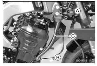
- Remove: (Right Side)
Coolant Reserve Tank (see Coolant Change in the Periodic Maintenance chapter)
Upper Engine Bracket Bolts [A]
Lower Engine Bracket Bolt [B] and Washer
Engine Bracket [C]
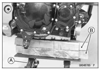
- Support the engine with a suitable stand [A].
- Put a plank [B] onto the suitable stand for engine balance.
- Remove:
Upper Engine Mounting Bolt [A] (Both Sides)
Middle Engine Mounting Nut [B] and Bolt
Lower Engine Mounting Nut [C]
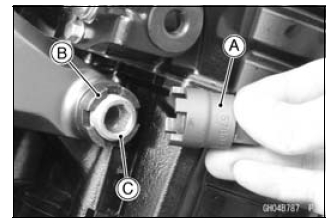
- Using the nut wrench [A], loosen the upper adjusting collar locknut [B].
Special Tool - Engine Mount Nut Wrench: 57001-1450
- Using the Hexagon Wrench, turn the adjusting collar [C] counterclockwise to make the gap between the engine and adjusting collar.
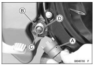
- Using the nut wrench [A], loosen the lower adjusting collar locknut [B].
Special Tool - Engine Mount Nut Wrench: 57001-1450
- Remove the lower engine mounting bolt [C].
- Using the Hexagon Wrench, turn the adjusting collar [D] counterclockwise to make the gap between the engine and adjusting collar.
- Using the stand, take out the engine.
Engine Installation
- Support the engine with a suitable stand.
- Put a plank onto the suitable stand for engine balance.
- Screw the adjusting collars [A] to the frame.
- Install the engine mounting bolts and nuts, following the specified
installing sequence.
- First, hang the drive chain over the output shaft just before moving the engine into its final position in the frame.
- Second, apply a non-parmanent locking agent to the threads of the
middle engine bracket bolts [A].
Install the middle engine bracket [B] and tighten the bolts.
Torque - Middle Engine Bracket Bolts: 25 N*m (2.5 kgf*m, 18 ft*lb)
- Third, insert the lower engine mounting bolt [C].
- Forth, install the collar [D], and insert the middle engine mounting bolt [E].
- Fifth, tighten:
Torque - Left Upper Engine Mounting Bolt [F]: 44 N*m (4.5 kgf*m, 32 ft*lb) - Sixth, tighten the upper adjusting collar locknut [G] and right upper engine mounting bolt [H] temporarily.
- Seventh, tighten the lower adjusting collar [I] until the clearance between the engine and frame comes to 0 mm.
- Eighth, tighten the lower adjusting collar locknut [J] and lower
engine mounting nut [K].
Torque -
Lower Adjusting Collar Locknut: 49 N*m (5.0 kgf*m, 36 ft*lb)
Lower Engine Mounting Nut: 44 N*m (4.5 kgf*m, 32 ft*lb) Special Tool - Engine Mount Nut Wrench: 57001-1450 - Ninth, tighten:
Torque - Middle Engine Mounting Nut [L]: 44 N*m (4.5 kgf*m, 32 ft*lb) - Tenth, install the left engine bracket [M], and tighten the mounting
bolts evenly.
Torque - Upper Engine Bracket Bolts [N]: 44 N*m (4.5 kgf*m, 32 ft*lb) Lower Engine Bracket Bolts [O]: 59 N*m (6.0 kgf*m, 36 ft*lb)
- Eleventh, install the right engine bracket [P] just like the left engine bracket.
- Twelfth, remove the right upper engine mounting bolt [H].
- Thirteenth, tighten the upper adjusting collar [Q] until the clearance between the engine and frame comes to 0 mm.
- Fourteenth, tighten the upper adjusting collar locknut [G].
Torque -
Upper Adjusting Collar Locknut: 49 N*m (5.0 kgf*m, 36 ft*lb)
Special Tool - Engine Mount Nut Wrench: 57001-1450 - Lastly, tighten:
Torque - Right Upper Engine Mounting Bolt [H]: 44 N*m (4.5 kgf*m, 32 ft*lb)
- Run the leads, cables and hoses correctly (see Cable, Wire, and Hose Routing section in the Appendix chapter).
- Install the removed parts (see appropriate chapters).
Torque - Engine Ground Cable Terminal Bolt: 9.8 N*m (1.0 kgf*m, 87 in*lb)
- Adjust:
Throttle Cables (see Throttle Control System Inspection in the Periodic Maintenance chapter)
Clutch Cable (see Clutch Operation Inspection in the Periodic Maintenance chapter)
Drive Chain (see Drive Chain Slack Inspection in the Periodic Maintenance chapter) - Fill the engine with engine oil (see Engine Oil Change in the Periodic Maintenance chapter).
- Fill the engine with coolant (see Coolant Change in the Periodic Maintenance chapter).
See also:
 Kawasaki Z1000SX - Service manual > Oil Pressure Switch
Oil Pressure Switch Removal Remove: Left Lower Fairing Assembly (see Lower Fairing Assembly Removal in the Frame chapter) Engine Oil (Drain, see Engine Oil Change in the Periodic Maintenance chapter) Switch Cover [A] Switch Terminal Bolt [B] Oil Pressure Switch [C]
 Rider's Manual BMW R 1250 GS GSA
 Owner's Manual Harley-Davidson Sportster XL1200X Forty-Eight
 Owner's Manual Honda CBR650R
 Service manual Honda CBR650
 Owner's Manual Honda PCX125
 Owner's Manual Kawasaki Z1000SX
 Service manual Kawasaki Z1000SX
 Owner's Manual Lexmoto Echo
 Owner's Manual Royal Enfield Interceptor 650
 Service manual Royal Enfield Interceptor 650
 Owner's Manual Yamaha MT-07