 Kawasaki Z1000SX - Service manual > Engine Top End
Valve Clearance Inspection
NOTE
- Valve clearance must be checked and adjusted when the engine is cold (room temperature).
- Remove:
Crankshaft Sensor Cover (see Crankshaft Sensor Removal in the Electrical System chapter)
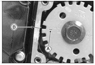
Cylinder Head Cover (see Cylinder Head Cover Removal in the Engine Top End chapter) - Turn the crankshaft, align the #1, 4 mark on the timing rotor with the
crankcase timing mark.
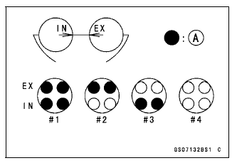
TDC Mark [A] for #1, 4 Pistons
Timing Mark [B] (Crankcase Halves Mating Surface)
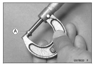
- Using the thickness gauge [A], measure the valve clearance between the cam and the valve lifter.
Valve Clearance
Standard:
Exhaust 0.22 - 0.31 mm (0.0087 - 0.0122 in.)
Intake 0.15 - 0.24 mm (0.0059 - 0.0094 in.)
NOTE
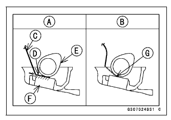
- Thickness gauge is horizontally inserted on the valve lifter.
Appropriateness [A]
Inadequacy [B]
Thickness Gauge [C]
Horizontally Inserts [D]
Cam [E]
Valve Lifter [F]
Hits the Valve Lifter Ahead [G]
- When positioning #4 piston TDC at the end of the compression stroke:
Intake Valve Clearance of #2 and #4 Cylinders
Exhaust Valve Clearance of #3 and #4 Cylinders
Measuring Valve [A]
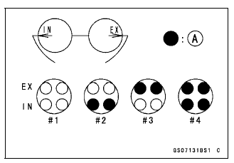
- When positioning #1 piston TDC at the end of the compression stroke:
Intake Valve Clearance of #1 and #3 Cylinders
Exhaust Valve Clearance of #1 and #2 Cylinders
Measuring Valve [A]
If the valve clearance is not within the specified range, first record the clearance, and then adjust it.
Valve Clearance Adjustment
- To change the valve clearance, remove the camshaft chain tensioner, camshafts and valve lifters. Replace the shim with one of a different thickness.
NOTE
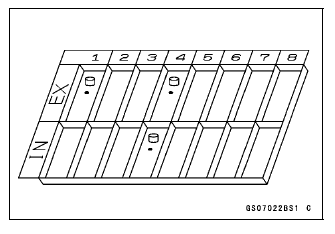
- Mark and record the locations of the valve lifters and shims so that they can be reinstalled in their original positions.
- Besides the standard shims in the valve clearance adjustment charts, the following shims may be installed at the factory. Although they are not available as spare parts, they can be used to adjust valve clearance.
Adjustment Shims
Thickness
3.225 mm
3.275 mm
3.325 mm
2.675 mm
2.725 mm
2.775 mm
2.825 mm
2.875 mm
2.925 mm
2.975 mm
3.025 mm
3.075 mm
3.125 mm
3.175 mm
- Clean the shim to remove any dust or oil.
- Measure the thickness of the removed shim [A].
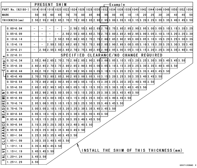
VALVE CLEARANCE ADJUSTMENT CHART INTAKE VALVE
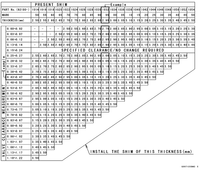
1. Measure the clearance (when engine is cold).
2. Check present shim size.
3. Match clearance in vertical column with present shim size in horizontal column.
4. Install the shim specified where the lines intersect. This shim will give the proper clearance.
Example: Present shim is 2.95 mm
Measured clearance is 0.45 mm
Replace 2.95 mm shim with 3.20 mm shim.
5. Remeasure the valve clearance and readjust if necessary.
VALVE CLEARANCE ADJUSTMENT CHART EXHAUST VALVE
1. Measure the clearance (when engine is cold).
2. Check present shim size.
3. Match clearance in vertical column with present shim size in horizontal column.
4. Install the shim specified where the lines intersect. This shim will give the proper clearance.
Example: Present shim is 2.95 mm.
Measured clearance is 0.47 mm.
Replace 2.95 mm shim with 3.15 mm shim.
5. Remeasure the valve clearance and readjust if necessary.
NOTICE Be sure to remeasure the clearance after selecting a shim according to the table. If the clearance is out of the specified range, use the additional shim.
If there is no valve clearance, use a shim that is a few sizes smaller, and remeasure the valve clearance.
- When installing the shim, face the marked side toward the valve lifter.
NOTICE Do not put shim stock under the shim. This may cause the shim to pop out at high rpm, causing extensive engine damage.
Do not grind the shim. This may cause it to fracture, causing extensive engine damage.
- Apply engine oil to the valve lifter surface and install the lifter.
- Install the camshaft (see Camshaft Installation in the Engine Top End chapter).
- Recheck the valve clearance and readjust if necessary.
- Install the removed parts (see appropriate chapters).
Air Suction System Damage Inspection
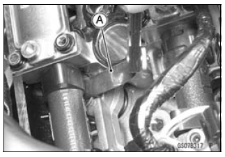
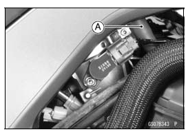
- Pull the air switching valve hose [A] out of the air cleaner housing.
- Start the engine and run it at idle speed.
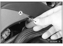
- Plug [A] the air switching valve hose end with your finger and feel
vacuum pulsing in the hose.
If there is no vacuum pulsation, check the hose line for leak. If there is no leak, check the air switching valve (see Air Switching Valve Unit Test in the Electrical System chapter) or air suction valve (see Air Suction Valve Inspection in the Engine Top End chapter).
See also:
 Kawasaki Z1000SX - Service manual > Cooling System
Coolant Level Inspection NOTE Check the level when the engine is cold (room or ambient temperature). Check the coolant level in the reserve tank [A] with the motorcycle held perpendicular (Do not use the sidestand).
Kawasaki Z1000SX - Service manual > Clutch
Clutch Operation Inspection Pull the clutch lever just enough to take up the free play [A]. Measure the gap between the lever and the lever holder. If the gap is too wide, the clutch may not release fully. If the gap is too narrow, the clutch may not engage fully. In either case, adjust it.
 Rider's Manual BMW R 1250 GS GSA
 Owner's Manual Harley-Davidson Sportster XL1200X Forty-Eight
 Owner's Manual Honda CBR650R
 Service manual Honda CBR650
 Owner's Manual Honda PCX125
 Owner's Manual Kawasaki Z1000SX
 Service manual Kawasaki Z1000SX
 Owner's Manual Lexmoto Echo
 Owner's Manual Royal Enfield Interceptor 650
 Service manual Royal Enfield Interceptor 650
 Owner's Manual Yamaha MT-07