 Royal Enfield Interceptor 650 - Service manual > Evaporative (EVAP) Emission Control System
General Description
Royal Enfield twin cylinder motorcycles are equipped with Evaporative (EVAP) Emission Control System.
Whenever the motorcycle is parked after a ride or in hot summer, in high day time temperatures, fuel vapors with hydrocarbons tend to escape into the atmosphere through the vent hole of the fuel tank cap.
The evaporative emission control system traps these fuel vapors and purges it into a charcoal canister. When the engine is running, the vapors from the charcoal canister is routed through a purge valve into the combustion chamber. These vapors are also monitored by the engine management system so as to ensure the exhaust emissions are within the specifications.
EVAP Components
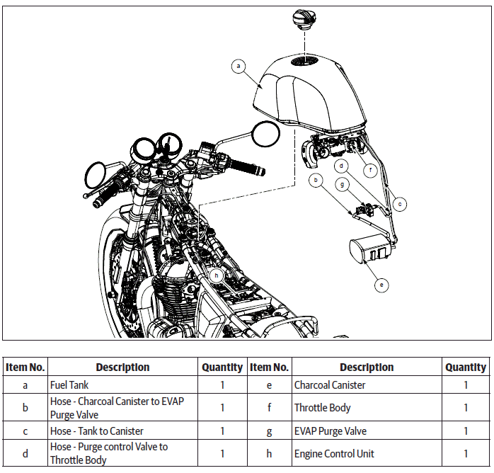
WARNING Before dismantling any part of the EVAP system, ensure the engine and exhaust systems are at ambient temperature. Evaporative fuel vapors are highly inflammable and explosive, which can result in serious injury and or fatal accidents.
WARNING DO NOT damage or puncture any part of the EVAP system like canister, purge valve etc. DO NOT blow high compressed air into the canister or purge valve as it can result in an explosion.
CAUTION Ensure the motorcycle is upright on a firm and flat surface.
- Ensure ignition key and engine stop switch are in OFF position.
- Disconnect battery negative (-) terminal.
- Before removing any part of the EVAP system, open fuel tank cap to release the pressure inside.
Evaporative (EVAP) Emission Control System
Dismantling
Charcoal Canister
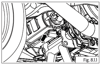
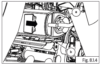
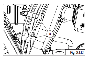
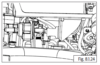
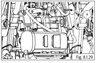
- The charcoal canister is located underneath the frame/above center stand mounting location.
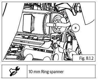
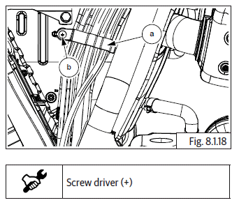
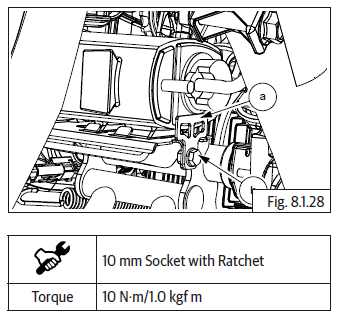
- Loosen and remove Hex flange head bolt (M6) (a) from EVAP canister bracket (b). EVAP canister bracket is located on RH side of motorcycle.
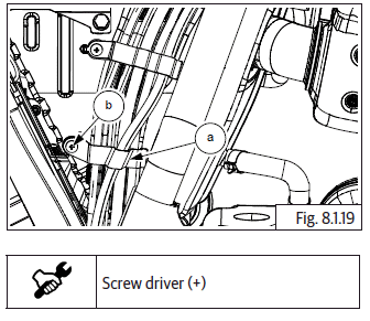
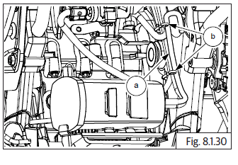
- Remove the canister retainer bracket (a) from frame (b).
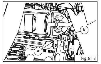
- Gently pullout canister (a) to release from locks on frame bracket (b).
CAUTION Do not apply excessive force to pull out canister with hoses as it will damage the canister and the hose pipes.
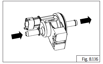
- Disconnect inlet (a) and outlet (b) hoses from canister (c).
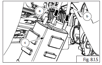
- Remove canister and store carefully.
EVAP Purge Valve
- Remove the following parts:
- Side panel RH.
- Rider seat.
- Side panel LH.
- Engine control unit (ECU).
- Rear mudguard.
- Infill mudguard.
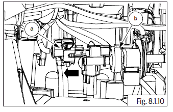
- Disconnect the roll over sensor connector.
- Release purge valve (a) from the bracket in battery carrier (b) by pushing backwards.
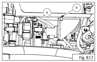
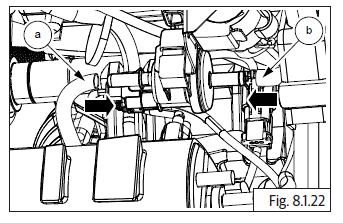
- Disconnect hose (a) from canister (b) to purge valve (c).
- Disconnect hose (a) from throttle body connected to purge valve (b).
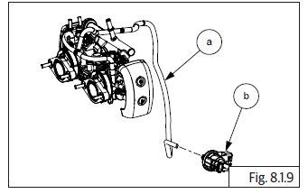
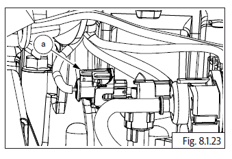
- Disconnect electrical connector (a) from purge valve (b).
- Remove purge valve and store carefully.
Hoses
- Remove fuel tank and disconnect hoses.
- Remove clamps (a) holding hoses to air filter housing on RH side.
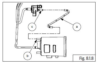
- Disconnect hose from purge valve (a) to connector (b).
- Disconnect hose (c) from connector to T-joint (d) near throttle body.
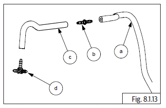
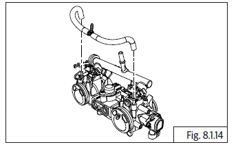
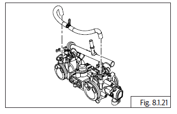
- Disconnect 2 Nos. hoses from throttle body connecting to T-joint.
NOTE
- Separate the connector and T-joint from the hoses and store carefully.
Inspection
Charcoal Canister
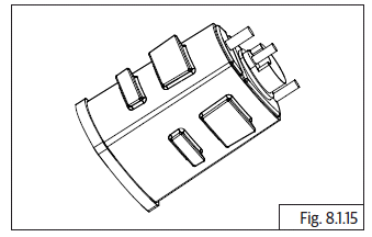
- Clean and inspect for any damage or crack on canister. Replace if necessary.
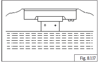
- Gently shake canister to feel if there is wet fuel inside. If suspected replace canister (weight 385 +- 5gms).
- Blow very low pressure air (5 psi) through the inlet port and check for the free flow of outlet side. If restricted or no air, replace the canister.
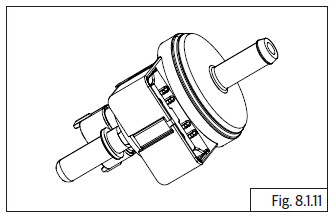
Purge Valve
- Clean and visually inspect the EVAP purge valve for any damage or crack.
- Check purge valve in EMS section, replace if found defective.
- Blow low pressure air (5 psi) through hose connecting to throttle body and check for pressure release through hose connecting to canister. If air releases, purge valve is defective and replace.
Hoses
- Check hose for any crack, pinch, wear out or hardening. Replace if defective.
- Replace hoses as mentioned in periodic maintenance schedule.
Hose Connectors
- Check for any damages or cracks and replace if defective.
Do's & Don'ts
- Do not fill fuel tank above anti-splash plate inside fuel tank as it will cause fuel to get into EVAP system.
- Do not use motorcycle if any part of EVAP system is damaged.
- Do check the EVAP system periodically for damages and leakages.
EVAP System Leak Test Procedure
- Ensure the systems hoses are connected correctly.
- Block the EVAP atmosphere breather.
- Block the LH side throttle body Hose, Purge.
- Connect a hose to the fuel tank to EVAP hose to allow a pressure to be applied.
- Connect another hose to the RH side throttle body Hose, Purge.
- Pressurise the system through both the Evap Canister atmosphere breather
and the RH side throttle body Hose, Purge at the same time as below:
- Fill at 20kPa for 20 Seconds.
- Stabilize, 50 Seconds.
- Drop less than 300 Pa over 5 minutes.
Assembly
Hoses
- Position upper clamp (a) correctly against air filter box assembly on RH, duly ensuring mounting holes are aligned. Ensure the brake hoses and EVAP hose are correctly located inside clamp.
- Locate screw (b) on mounting hole of clamp and tighten clamp to air filter housing.
- Position lower clamp (a) correctly against air filter box assembly on RH side, duly ensuring mounting holes are aligned. Ensure brake hoses and wiring harness are correctly located inside clamp.
- Locate screw (b) on mounting hole of clamp and tighten clamp to air filter housing.
NOTE
- Please ensure the EVAP hoses are routed properly and ensure they DO NOT get pinched or damaged.
- Locate connector (b) on the hose (a) going to purge valve.
- Connect small hose (c) to connector (b).
- Connect T-joint (d) to small hose (c).
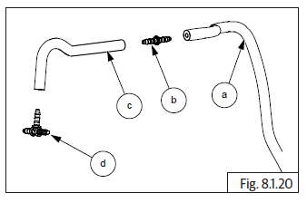
- Connect 2 Nos. hoses on either end of T-joint to connect to throttle body and connect the other end of the hoses to the throttle body LH and RH.
EVAP Purge Valve
- Connect throttle body hose (a) to outlet near wiring coupler in purge valve.
- Connect small hose (b) to inlet of purge valve from canister.
- Connect the electrical connector (a) to purge valve.
- Position battery carrier bracket in the frame and locate purge valve on battery carrier bracket bottom.
- Ensure purge valve is located properly on battery carrier bracket.
- Assembly the following parts:
- Connect roll over sensor connector.
- Infill mudguard.
- Rear mudguard.
- Engine control unit (ECU).
- Side panel LH.
- Rider seat.
- Side panel RH
Charcoal Canister
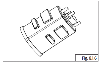
- Connect hose (a) from fuel tank to center pipe marked "tank" in canister.
- Connect hose from purge valve (b) to outer pipe marked "purge" in canister (c).
- Ensure hoses are seated properly.
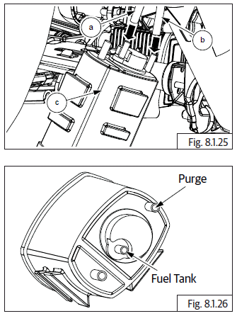
NOTE
- Do not connect anything to the third pipe in the canister. It is a dummy pipe.
- Locate canister (a) on bracket (b) in frame. Push it completely to lock in place.
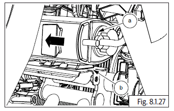
- Locate retainer bracket (a) on canister, align mounting hole to frame and tighten with Hex flange bolt (M6) (b).
- Secure the hoses through frame upper and lower wire guides (a).
- Connect breather hose (a) into canister and ensure it is properly routed on frame upper and lower wire guides (b).
- Reassemble the following parts:
- Infill mudguard.
- Connect roll over sensor connector.
- Tighten rear mudguard front mounting torx screws.
- Rear wheel.
- ECU and connect wiring connectors.
- Battery.
- Fuel tank.
- Side panel LH.
- Seat.
- Side panel RH
See also:
 Royal Enfield Interceptor 650 - Service manual > Fuel System
General Description The fuel leaves the tank through the fuel pump (a) and then passes through the fuel filter (b). Next is a T - junction (c) which splits the fuel flow to the throttle body (d) and return hose to the fuel pump (e). The return hose is for pressure regulation and fuel flows through return hose only if the pressure is above 3.5 bar.
 Rider's Manual BMW R 1250 GS GSA
 Owner's Manual Harley-Davidson Sportster XL1200X Forty-Eight
 Owner's Manual Honda CBR650R
 Service manual Honda CBR650
 Owner's Manual Honda PCX125
 Owner's Manual Kawasaki Z1000SX
 Service manual Kawasaki Z1000SX
 Owner's Manual Lexmoto Echo
 Owner's Manual Royal Enfield Interceptor 650
 Service manual Royal Enfield Interceptor 650
 Owner's Manual Yamaha MT-07