 Royal Enfield Interceptor 650 - Service manual > Fuel System
General Description
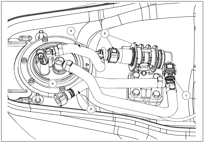
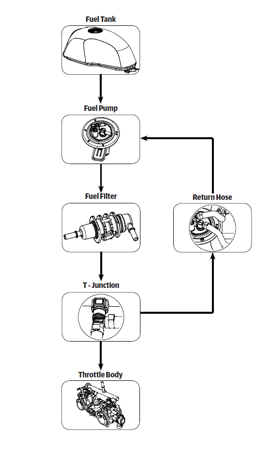
The fuel leaves the tank through the fuel pump (a) and then passes through the fuel filter (b). Next is a T - junction (c) which splits the fuel flow to the throttle body (d) and return hose to the fuel pump (e). The return hose is for pressure regulation and fuel flows through return hose only if the pressure is above 3.5 bar.
Fuel System Flowchart
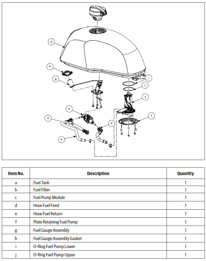
Fuel System
WARNING Gasoline is extremely flammable and highly explosive. Please handle with care. Improper handling can lead to fatal accident or serious injury. Always drain/fill fuel only in a well ventilated area. Ensure there is no scope for flames or sparks near by while draining/filling fuel.
CAUTION Make sure the fuel pressure is relieved before disconnecting the fuel connection.
CAUTION Ensure the motorcycle is upright on a firm and flat surface.
Dismantling
Fuel Tank
- Ensure the ignition and stop switches are in OFF position.
- Remove the fuel tank cap. Drain fuel completely from fuel tank.
- Remove the following parts:
- Remove side panel RH.
- Remove rider seat.
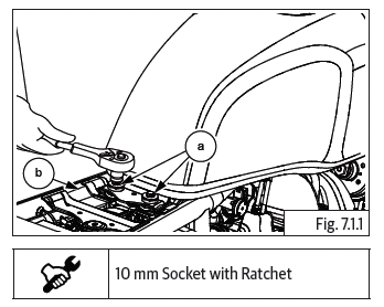
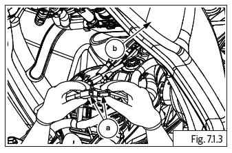
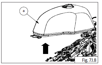
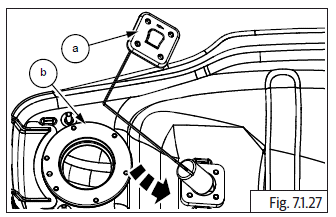
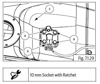
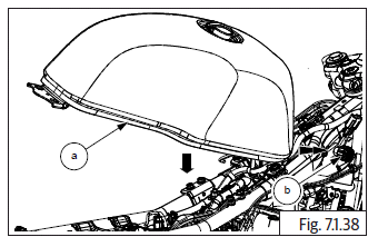
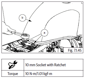
- Loosen and remove 2 Nos. Hex head bolts (M6) (a) from rear end of fuel tank on frame (b).
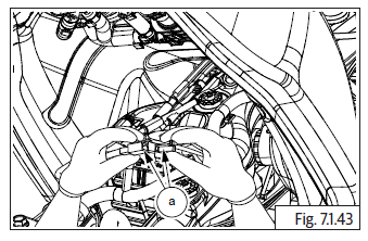
Fuel Pump Connector and Fuel Level Sensor
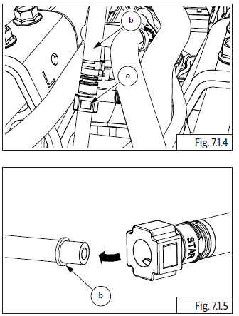
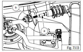
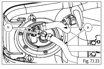
- Gently lift fuel tank (a) upwards and pull backwards slightly.
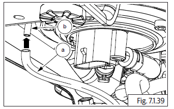
- Disconnect fuel pump connector (b) from fuel tank.
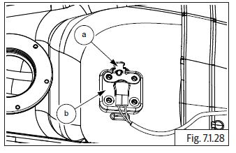
CAUTION DO NOT lift the tank too much to prevent damage to connectors and brake hoses.

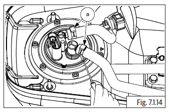
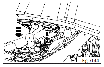
- Disconnect fuel level sensor connector (a) from fuel tank (b).
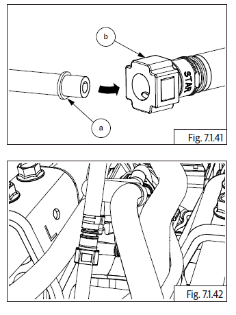
Fuel Hose (Fuel Pump to Injector)
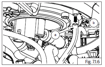
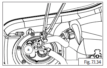
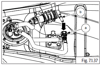
- Clean quick fix adapter area and disconnect by pressing lock button (a). Remove fuel hose (b).
EVAP Connections to Fuel Tank
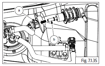
- Disconnect EVAP connection hose (a) from fuel tank (b).
Drain Hose
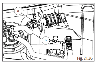
- Disconnect drain hose connection (a) from fuel tank (b).
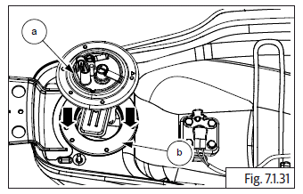
- Gently remove fuel tank (a) from frame.
Fuel Filter
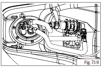
- Invert fuel tank to access fuel pump and fuel float.
- Ensure the tank top/side surfaces DO NOT get damaged or scratched while removing fuel pump/ float. Provide adequate protection to fuel tank.
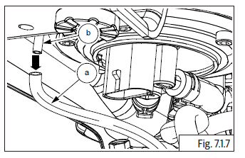
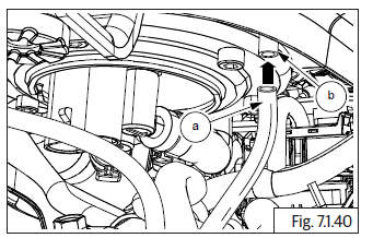
- Press lock to release quick connector (a) from fuel filter outlet (b).
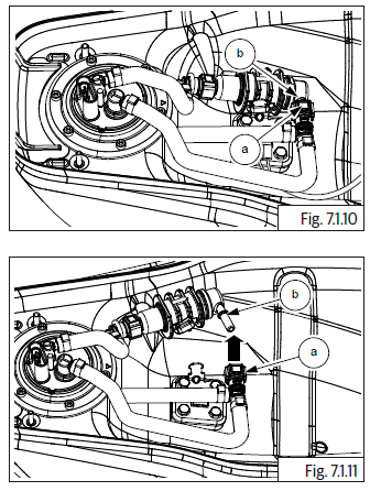
- Press lock to release quick connector (a) from fuel filter inlet (b).
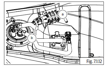
- Remove fuel filter (a) from fuel pump inlet hose (b).
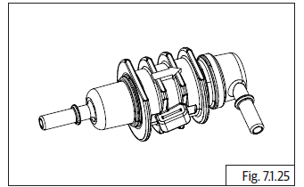
Fuel Pump
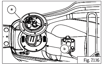
- Loosen worm clips (a) on the hoses and remove hose from fuel pump.
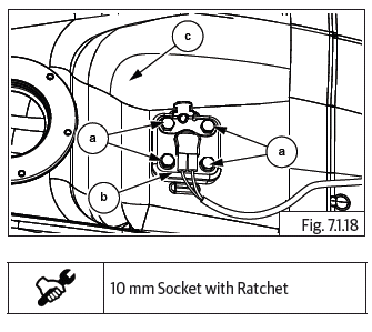
- Loosen and remove 6 Nos. Hex socket head bolts (M5) (a) holding fuel pump (b) to tank (c).
- Gently pull out the fuel pump (a) from fuel tank (b).
- Remove O-rings (a) and (b) from fuel pump.
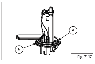
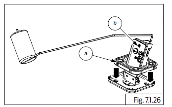
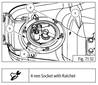
Fuel Float
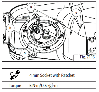
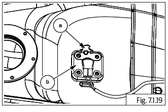
- Loosen and remove 4 Nos. Hex head flange bolts (M6) (a) to remove fuel float (b) from fuel tank (c).
- Remove fuel filter bracket (a) from fuel float (b).
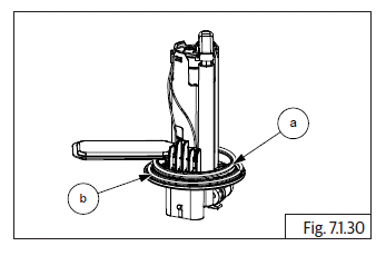
- Gently lift (1) and rotate clockwise (2) to take out the complete float unit (a) from tank (b).
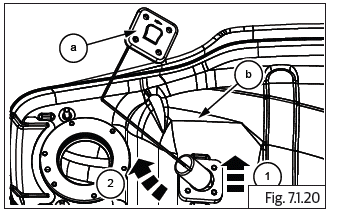
CAUTION Ensure the float unit does not gets damaged or bent while removing from fuel tank. Store fuel float unit carefully. Do not disturb the level of the float unit as it will seriously affect fuel level indication.
- Remove gasket (a) from float unit (b).
Inspection
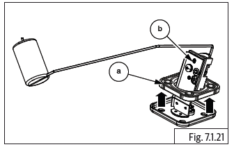
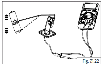
Fuel Float
- Check resistance at float unit pins at lower position.
- Check the resistance at float unit pins at higher position.
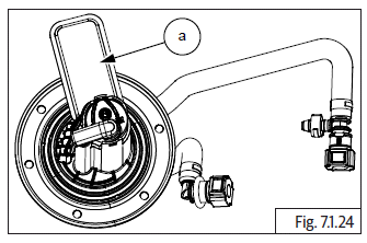
- Inspect float assembly for fuel ingress. Replace if fuel float assembly is punctured.
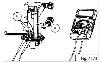
Fuel Pump
- Check resistances at fuel pump (a) terminals (b). Replace if resistances are out of specifications.
- Replace fuel stainer (a) whenever it is removed.
Fuel Filter
- Replace fuel filter whenever it is removed.
- Replace following whenever fuel system is dismantled:
- O-rings and gaskets
- Rubber hoses
- Fuel filters
Assembly
Fuel Float
- Locate gasket (a) into float unit (b).
- Insert fuel float unit (a) on fuel tank (b) with float facing towards front of fuel tank. Slightly Rotate anti-clockwise while inserting float in fuel tank.
- Assemble bracket (a) on fuel float unit (b).
- Locate and tighten 4 Nos. Hex head flanged bolts (M6) (a) on bracket to assemble fuel float unit (b) on fuel tank (c).
Fuel Pump
- Locate O-rings (a) and (b) on fuel pump. Ensure it is seated properly.
- Assemble fuel pump (a) into tank (b) with outlet and return pipes facing towards front of the tank.
- Locate and tighten 6 Nos. Hex socket head bolts (M5) (a) to assemble fuel pump (b) on fuel tank (c).
- Insert hoses (a) on fuel pump assembly (b).
- Tighten with clips (a). Ensure the clips are locked properly on the hoses.
Fuel Filter
- Assemble fuel filter (a) on fuel pump inlet hose (b).
- Ensure arrow mark direction on fuel filter is facing towards inlet pipe.
- Insert filter quick connector (a) into the fuel filter inlet (b). Ensure locks seated properly.
- Insert quick connector (a) into filter outlet hose (b) and ensure lock is seated properly.
Fuel Tank
- Hold and slide fuel tank (a) into frame guide (b) and ensure bush in fuel tank are aligned into guide in frame.
Drain Hose
- Gently lift fuel tank and connect drain hose connection (a) to fuel tank (b).
EVAP Connections to Fuel Tank
- Connect EVAP connection hose (a) to fuel tank (b).
Fuel Hose (Fuel Pump to Injector)
- Connect fuel hose (a) into quick fix connector (b) and ensure lock button is locked with a click sound.
- Connect fuel level sensor connector (a).
Fuel Pump Connector and Fuel Level Sensor
- Connect fuel pump connector (a) into fuel pump (b).
- Gently lower the fuel tank into frame.
- Locate and tighten 2 Nos. Hex head bolts (M6) (a) on rear end of fuel tank (b).
NOTE
- Switch ON and OFF the ignition twice and visually check for any fuel leakage or wet on the tank and components, If anything found, inspect and rectify the issue.
See also:
 Royal Enfield Interceptor 650 - Service manual > Steering Stem Assembly into Frame Head Tube
Insert the dust seal (a) and roller bearing (b). Assemble bearing (a) with special tool (b).
Royal Enfield Interceptor 650 - Service manual > Evaporative (EVAP) Emission Control System
General Description Royal Enfield twin cylinder motorcycles are equipped with Evaporative (EVAP) Emission Control System. Whenever the motorcycle is parked after a ride or in hot summer, in high day time temperatures, fuel vapors with hydrocarbons tend to escape into the atmosphere through the vent hole of the fuel tank cap.
 Rider's Manual BMW R 1250 GS GSA
 Owner's Manual Harley-Davidson Sportster XL1200X Forty-Eight
 Owner's Manual Honda CBR650R
 Service manual Honda CBR650
 Owner's Manual Honda PCX125
 Owner's Manual Kawasaki Z1000SX
 Service manual Kawasaki Z1000SX
 Owner's Manual Lexmoto Echo
 Owner's Manual Royal Enfield Interceptor 650
 Service manual Royal Enfield Interceptor 650
 Owner's Manual Yamaha MT-07