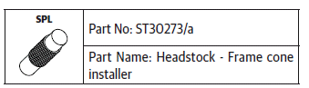
 Royal Enfield Interceptor 650 - Service manual > Steering Stem Assembly into Frame Head Tube
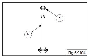
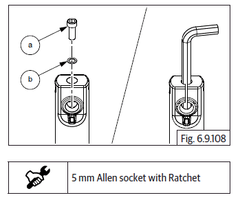
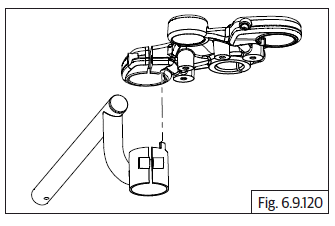
- Insert the dust seal (a) and roller bearing (b).
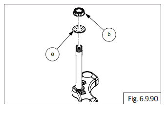
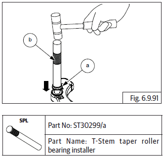
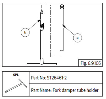
- Assemble bearing (a) with special tool (b).
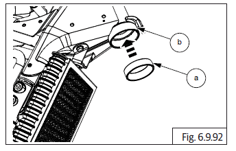
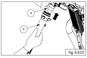
Tapered Roller Bearing Cups on Frame Head Tube
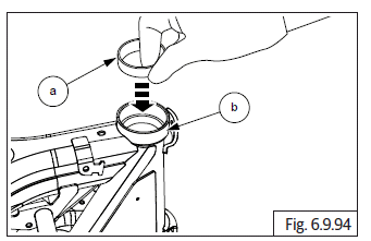
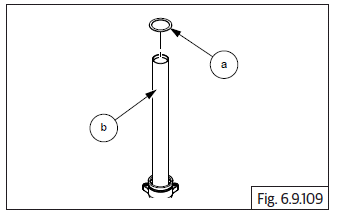
- Locate bottom bearing cup (a) into frame head tube bottom (b).
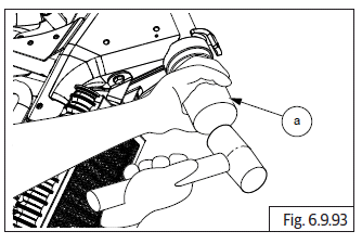
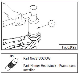
- Locate special tool on bearing cup bottom and tap bearing cup into frame head tube.
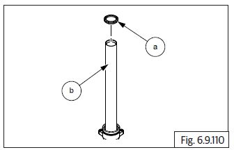
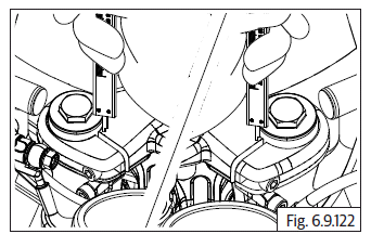
- Locate top bearing cup (a) on the frame head tube top (b).
- Locate special tool on bearing cup top and tap bearing cup into frame head tube.
Steering Stem on Frame Head Tube
- Apply Royal Enfield recommended grease on the bearing cups inner surface.
- Insert steering stem (a) into frame head tube from the bottom.
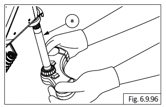
CAUTION Support steering stem from bottom. DO NOT allow the steering stem to drop out of frame head tube.
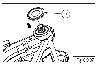
- Assemble headstock seal with the taper facing downwards (a).
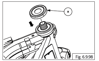
- Assemble headstock cover (a) with the cup facing downwards.
- Assemble stem nut (M12) (a) on steering stem and tighten.
Check the following
- Check the free movement of steering stem from left to right.
- Check axial play of steering stem at center, extreme left and right positions.
- Check lateral play of steering stem at center, extreme left and right positions.
- Tighten or loosen stem nut to ensure no axial or lateral movement is present and the steering movement is smooth.
CAUTION DO NOT over tighten the nut. Over/under torquing will lead to improper adjustment of steering stem.
Check for smooth turning in left and right directions and tighten just sufficiently.
Top Yoke on steering stem
- Locate top yoke (a) over stem nut and ensure it is seated fully.
- Assemble hex socket bolt (M8) (a) into top yoke from RH side and tighten just sufficiently. DO NOT TIGHTEN THE BOLT TO TORQUE.
Front Fork Sub Assembly LH and RH
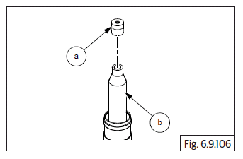
- Assemble spring (a) into piston from the bottom end (b).
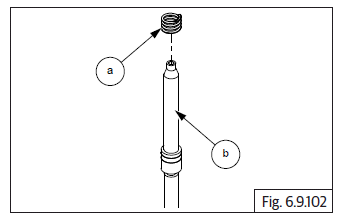
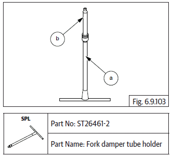
- Locate special tool (a) on piston (b) with the piston facing upwards.
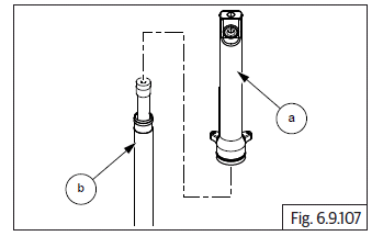
- Assemble slide bush (a) into main tube (b) from fork top.
- Assemble fork main tube (a) on piston (b) with the threads on the main tube inner facing downwards. Ensure the piston is guided out of the main tube.
- Assemble taper oil lock (a) on piston (b). Apply little grease to lock on its place.
- Assemble bottom tube top (a) over main tube (b). Ensure it is seated on taper oil lock.
- Locate hex socket head screw (M6) (a) along with washer (b) into mounting hole in bottom tube and tighten to torque.
- Remove the special tool.
- Insert washer (a) on the main tube (b) and ensure proper seating into the bottom tube.
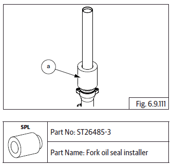
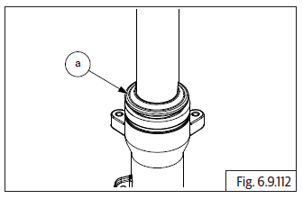
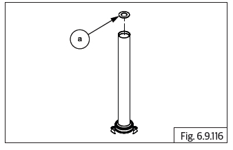
- Assemble oil seal (a) on main tube (b) with the lip facing upwards.
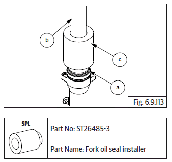
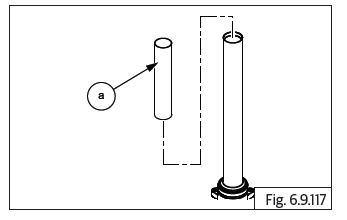
- Locate special tool (a) on main tube and drive oil seal into bottom tube till it is seated fully and the seal clip groove in bottom tube is visible.
- Remove special tool from fork inner tube.
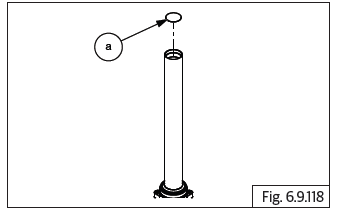
- Assemble seal clip (a) over oil seal and ensure it is seated properly on the grove in bottom tube.
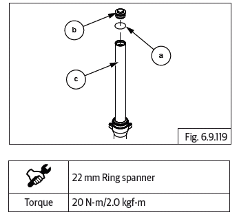
- Assemble dust seal (a) from main tube top (b) with closed ends upwards. Using special tool (c), drive dust seal into bottom tube till it is flush with top surface of bottom tube.
- Ensure free up and down movement of the main tube into bottom tube.
- Holding bottom tube, gently pull out main tube to its maximum stop ends position.
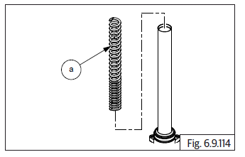
- Insert spring (a) into main tube with its closed coils facing downwards.
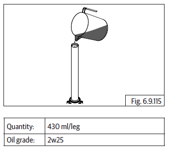
- Fill recommended fork oil into main tube.
- Replace with new oil whenever the oil drained from fork.
- Check oil quantity and fill with recommended fork oil with specified grade. Specified oil grade: 10Wt (Fork Oil Quantity = 430 ml per fork).
- Insert steel plate (a) into main tube over spring top.
- Assemble spacer tube (a) into main tube.
- Assemble plain washer (a) over spacer tube.
- Locate O-ring (a) on cap nut (b), position it over washer correctly, gently push down cap nut till threads engage in main tube (c) and tighten fully.
CAUTION Ensure thread are engaged correctly to prevent damage to cap nut/main tube threads
Front Fork LH and RH Assembly on Motorcycle
- Ensure pinch bolts on LH and RH sides of the steering stem and top yoke are sufficiently loose.
- Ensure the steering stem and top yoke fork mounting holes are aligned.
- Position headlamp holder RH between steering stem and top yoke.
NOTE
- Ensure pinch bolt on headlamp RH is loose.
For continental GT
- Position clip on RH between headlamp holder and top yoke duly ensuring peg on clip on is located into top yoke correctly.
NOTE
- Ensure the pinch bolt on clip on is loose.
- Insert fork assembly RH (a) into steering stem (b), headlamp holder, handlebar clip on and top yoke.
- Gently tighten one of the pinch bolt in steering stem RH to prevent fork from dropping down.
- Repeat above process to assemble fork assembly LH.
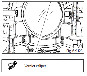
- Ensure fork assembly RH and LH top is 10 mm above and hex cap nut is above the top yoke.
- Tighten 4 Nos. Hex socket head bolts (M8) (a) each on the steering stem and top yoke LH and RH sides.
- For Continental GT: Ensure the locking peg of clip on RH/LH are correctly seated in the slot in top yoke and tighten pinch bolts.
- For Interceptor: Position handlebar on top yoke, ensure the reference marks on the handlebar are correctly aligned with mounting bracket face on top yoke.
- Assemble clamp handlebar and tighten with 4 Nos. Hex socket screws (M8) (a).
- Position headlamp holder such that it is 58 mm from the steering stem top face.
- Tighten the 2 Nos. pinch bolt (M6) (a) in headlamp holder.
- Repeat above process for correct positioning of other headlamp holder.
- Reassemble the following parts:
- Assemble Ignition switch and connect wiring connector.
- Instrument cluster and connect wiring connector.
- Trafficators LH and RH and connect wiring coupler.
- Headlamp assembly.
- Headlamp housing between headlamp holder LH and RH.
- Front number plate - India.
- Front mudguard.
- Wheel caliper on fork end LH.
- ABS wheel speed sensor on fork end LH.
- Position brake hose and ABS wheel speed sensor in the clamps on the LH side.
- Locate wheel speed sensor on RH side of the wheel hub, position front wheel between fork ends, ensure speed sensor is correctly positioned against fork end RH. Insert front wheel axle into fork end and tighten to torque.
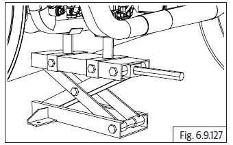
- Support motorcycle underneath cradle frame such that front wheel is off the ground by minimum 6 inches/15 cm.
- Turn handlebar to extreme left and right position and check for free and smooth rotation.
- Hold the front wheel straight ahead, check for any play.
- Gently push front wheel upwards and release, check for any play.
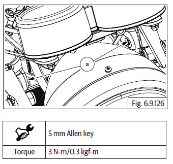
- Tighten pinch bolt (a) on top yoke to torque.
Steering Stem Play Adjustment
- Ensure the motorcycle is on a firm and flat surface.
- Ensure front wheel is off the ground. Turn handlebar to extreme LH and RH side to check for free movement. Hold handlebar in straight position and gently lock the motorcycle keeping a finger underneath top yoke to check for any axial or lateral movement.
- If movement is found adjust as follows:
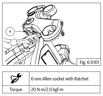
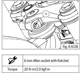
- Loosen pinch bolt (a) on top yoke.
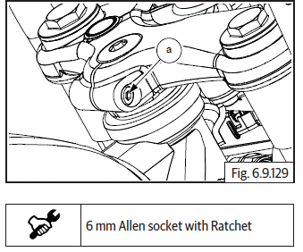
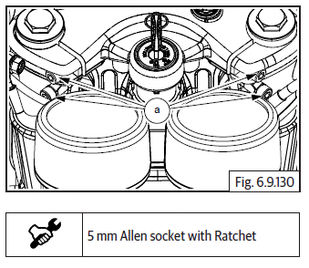
- Loosen 4 Nos. Pinch bolts (M6) (a) on top yoke LH and RH side (fork main tube area).
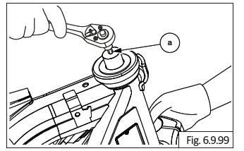
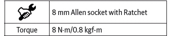
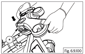
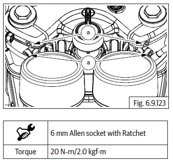
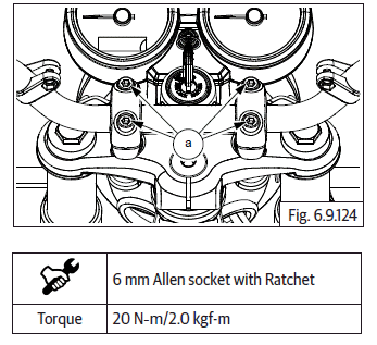
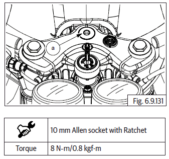
- Locate Allen socket on stem nut (M12) (a) and tighten gently.
NOTE
- After a set torque of 8 N-m do not steer the motorcycle.
- Check for free rotation and no axial or lateral movements.
- Tighten pinch bolt on top yoke and stem nut.
- Tighten 4 Nos. pinch bolts to specified torque 20 N-m/2.0 kgf-m.
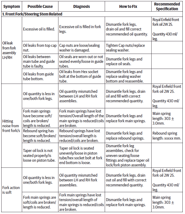
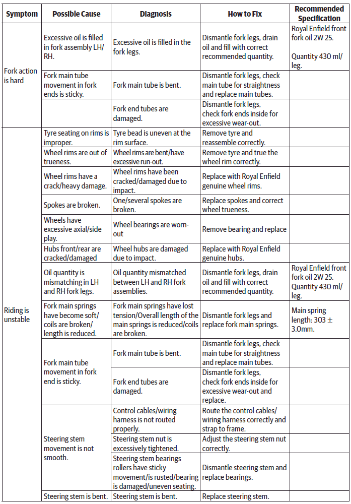
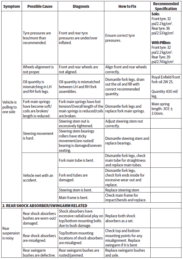
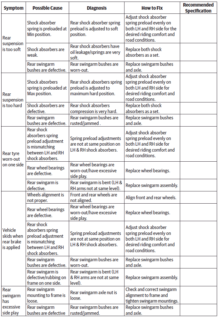
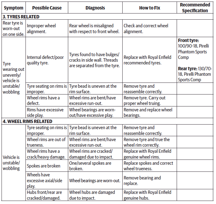
Troubleshooting
See also:
 Royal Enfield Interceptor 650 - Service manual > Steering Stem Assembly from Frame Head Tube
CAUTION Ensure the motorcycle is upright on a firm and flat surface. Locate a scissor jack (a) under the cradle frame (b) and lift motorcycle such that the front wheel is off the ground by minimum 6 inches (or 15 cm). Ensure ignition and stop switch are in off position. Remove the following parts: Front wheel. Release brake hose and wheel speed sensor wires from the clips. Wheel caliper from fork end LH.
Royal Enfield Interceptor 650 - Service manual > Fuel System
General Description The fuel leaves the tank through the fuel pump (a) and then passes through the fuel filter (b). Next is a T - junction (c) which splits the fuel flow to the throttle body (d) and return hose to the fuel pump (e). The return hose is for pressure regulation and fuel flows through return hose only if the pressure is above 3.5 bar.
 Rider's Manual BMW R 1250 GS GSA
 Owner's Manual Harley-Davidson Sportster XL1200X Forty-Eight
 Owner's Manual Honda CBR650R
 Service manual Honda CBR650
 Owner's Manual Honda PCX125
 Owner's Manual Kawasaki Z1000SX
 Service manual Kawasaki Z1000SX
 Owner's Manual Lexmoto Echo
 Owner's Manual Royal Enfield Interceptor 650
 Service manual Royal Enfield Interceptor 650
 Owner's Manual Yamaha MT-07