 Royal Enfield Interceptor 650 - Service manual > Steering Stem Assembly from Frame Head Tube
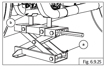
CAUTION Ensure the motorcycle is upright on a firm and flat surface.
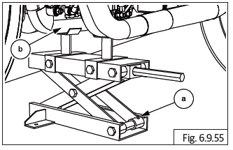
- Locate a scissor jack (a) under the cradle frame (b) and lift motorcycle such that the front wheel is off the ground by minimum 6 inches (or 15 cm).
- Ensure ignition and stop switch are in off position.
- Remove the following parts:
- Front wheel.
- Release brake hose and wheel speed sensor wires from the clips.
- Wheel caliper from fork end LH.
Support caliper suitably.
- Wheel speed sensor from the fork end LH. Support wheel speed sensor suitably.
- Front mudguard.
- Front number plate.
- Headlamp assembly and housing.
- Trafficators.
- Fork LH and RH.
- Disconnect ignition switch connector.
- Disconnect instrument cluster wiring connector.
- Instrument cluster from top yoke.
For Interceptor
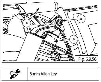
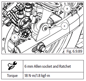
- Loosen and remove 4 Nos. Hex socket head screws (M8) (a) from clamp holding handlebar to top yoke.
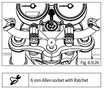
CAUTION Support handlebar suitably to prevent damage to master cylinder and controls.
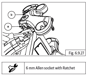
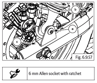
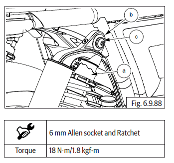
- Loosen and remove Hex socket head bolt (M8) (a) from the right side rear of top yoke (b).
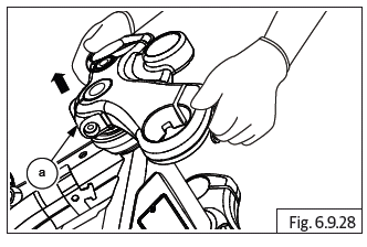
- Ensure free movement of top yoke in steering stem and gently pull out top yoke (a) from steering stem.
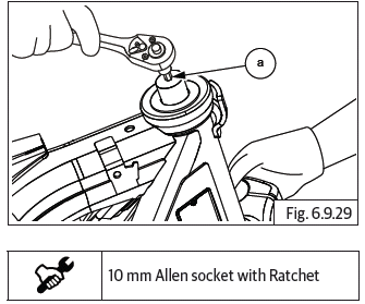
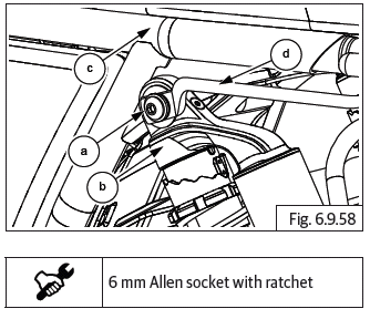
- Turn steering stem to extreme left, loosen and remove stem nut (M12) (a).
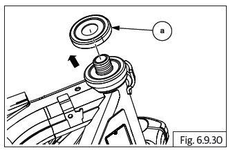
CAUTION Support steering stem from bottom. DO NOT allow the steering stem to drop out of frame head tube.
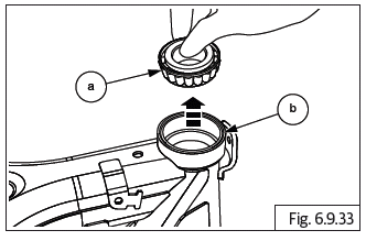
- Hold steering stem from bottom and remove cover head stock (a).
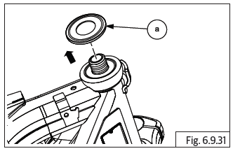
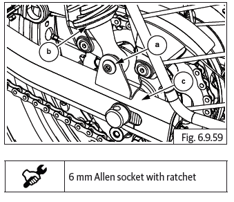
- Hold steering stem from bottom and remove seal head stock (a).
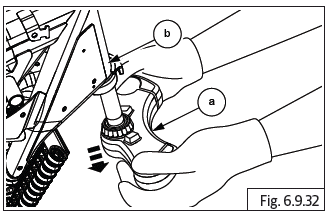
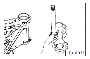
- Gently pull out steering stem (a) from frame head tube bottom (b).
CAUTION DO NOT tap or use force to remove steering stem from frame head tube.
Tapered Bearing Cups from Frame Head Tube
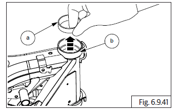
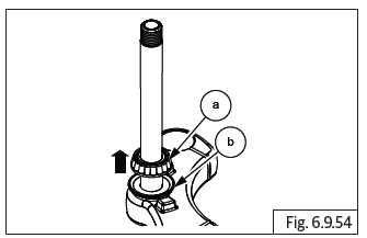
- Gently pull out tapered bearing (a) from frame head tube top (b).
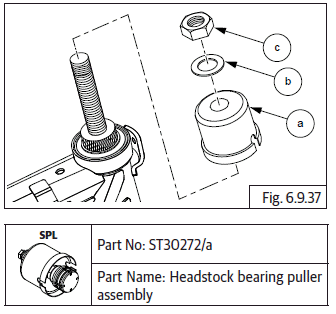
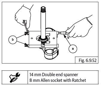
- Install special tool (a) on frame head tube top (b). Ensure tool is seated properly.
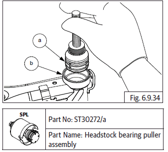
- Rotate tool in clockwise direction and tighten lock nut (a).
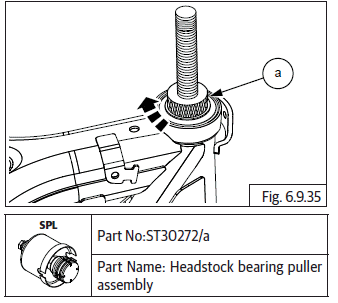
- Hold lock nut (a) and tighten threaded strut (b) till resistance is felt and strut cannot be turned further.
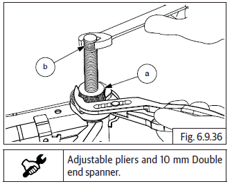
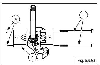
- Assemble puller cup (a), washer (b) and hex nut (M16) (c) on strut as shown.
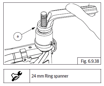
- Tighten hex nut (M16) (a) in clockwise direction till bearing tool assembly comes out of frame head tube and hex nut rotates free.
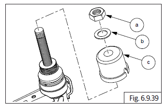
- Remove hex nut (a), washer (b) and cup (c) from strut as shown.
- Remove tool (a) from frame head tube top (b).
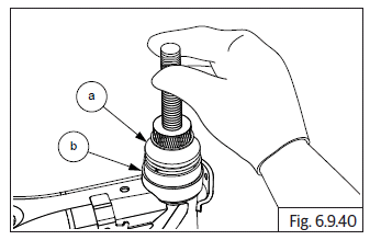
- Remove bearing cup (a) from the frame head tube top (b).
- Repeat procedures mentioned above for removing bearing cup from frame head tube bottom.
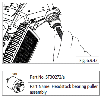
Bottom Roller Bearing from Steering Stem
- Use bearing puller T-stem to remove the bearing from T-stem.
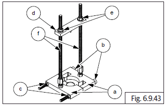
- Bottom Plates
- Bolts
- Nuts
- Top Plate
- Top Plate Nuts
- Long Studs
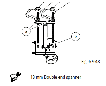
- Assemble two halves of bottom plate (a) below bearing in steering stem.
- Ensure the mounting holes are aligned and insert long bolts (b) and nuts (c) into the bottom plates.
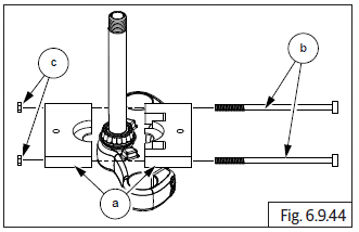
- Hold 2 Nos. bolts (a) suitably and tighten nuts (b) just sufficiently.
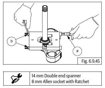
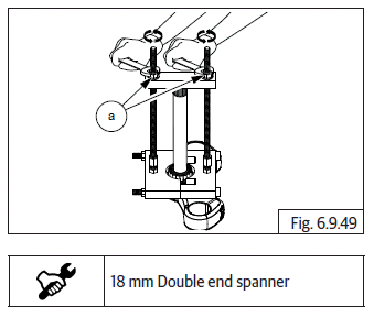
- Ensure mounting holes are aligned and insert long bolts (a) into bottom plates and tighten lock nuts (b).
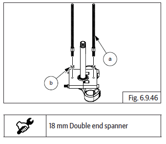
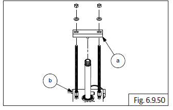
- Locate top plate (a) above steering stem duly ensuring long studs from bottom plate (b) are correctly positioned into top plate.
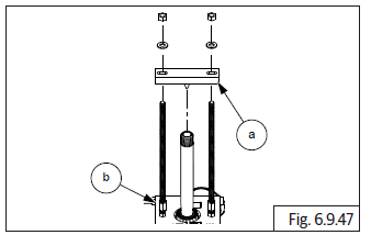
- Tighten 2 Nos. nuts (a) on top plate evenly to pull out the tapered roller bearing (b) from steering stem.
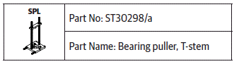
Dismantle Bearing Puller T-Stem As Follows:
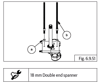
- Loosen 2 Nos. nuts (a) on top plate evenly to pull out the tapered roller bearing from the steering stem.
- Remove top plate (a) above steering stem duly ensuring the long studs from bottom plate (b).
- Loosen lock nuts (a) remove long studs (b) from bottom plates.
- Hold 2 Nos. bolts (a) suitably and loosen nuts (b) just sufficiently.
- Remove two bolts (a), nuts (b) and halves (c).
- Remove bottom roller bearing (a) from steering stem dust seal (b).
Shock absorber
CAUTION Ensure the motorcycle is upright on a firm and flat surface.
- Locate a scissor jack (a) under the cradle frame (b) and support motorcycle such that the rear wheel is on the ground.
- Loosen and remove button head bolt (M8) (a) from shock absorber (b) top and frame (c) RH.
- Support rear wheel, loosen and remove button head screw (M8) (a) from the shock absorber bottom (b) and swingarm RH (c).
- Gently remove RH shock absorber from swingarm bracket.
- Loosen grab handle mounting on frame.
- Loosen and remove button head bolt (M8) (a) from shock absorber (b) top and frame (c) LH. Remove grab handle (d).
- Loosen and remove button head bolt (M8) (a) from shock absorber (b) bottom and swingarm (c) LH.
- Gently remove LH shock absorber from swingarm bracket.
CAUTION Ensure motorcycle is supported suitably at the rear end after removing both shock absorbers to prevent motorcycle from tipping over and falling down.
Swingarm
- Remove the following parts:
- Rear wheel.
- Rear shock absorber LH and RH.
CAUTION Ensure the motorcycle is upright on a firm and flat surface. Support the motorcycle firmly while removing the swingarm.
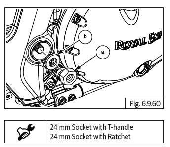
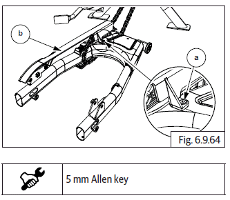
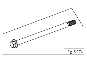
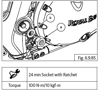
- Hold spindle bolt (M16) in frame LH side and loosen and remove hex nut (M16) (a) with washer (b) from RH side.
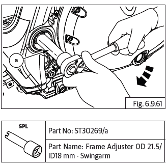
- Insert special tool (a) into frame RH side and loosen the adjuster swingarm in clock wise direction (Left hand thread).
CAUTION Adjuster is a left hand thread. Wrong rotation may damage the threads and hub.
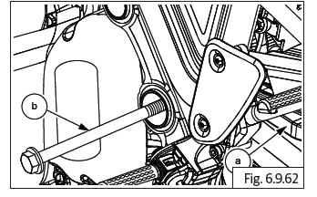
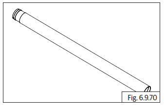
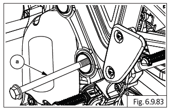
- Provide suitable support below swingarm (a) and pull out spindle (b) from LH side.
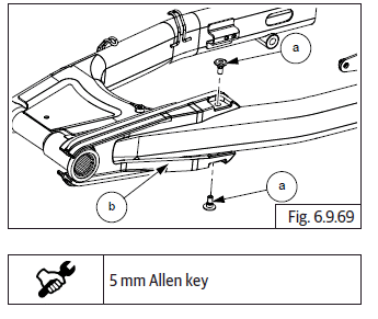
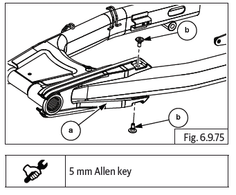
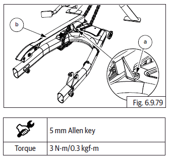
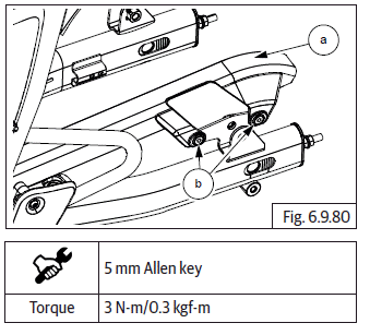
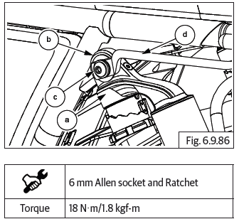
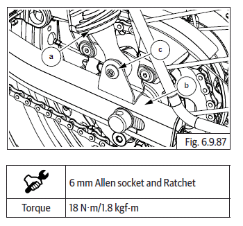
- Loosen and remove 2 Nos. Hex socket button bolts (M6) (a) to separate chain guard (b) from swingarm RH.
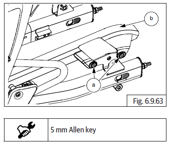
- Loosen and remove Hex socket button head bolt (M6) (a) to separate chain guard (b) from swingarm.
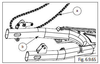
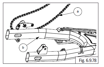
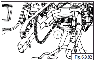
- Rotate swingarm slightly and release drive chain (a) from swingarm (b).
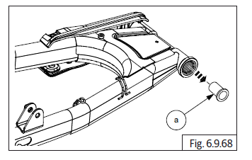
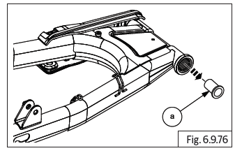
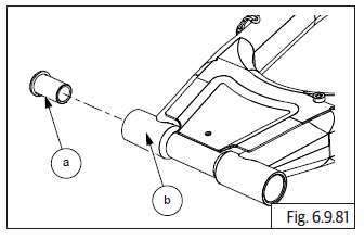
- Remove end cup (a) from swingarm LH and RH.
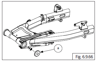
- Remove bearing sleeve (a) from swingarm LH.
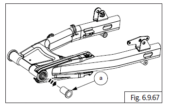
- Remove bearing sleeve (a) from swingarm RH.
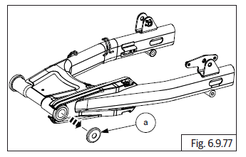
- Loosen and remove 2 Nos. Hex socket button head bolts (M6) (a) to remove chain rubber strip (b).
NOTE
- Needle roller bearing inside swingarm cannot be removed/replaced. In the event of bearing failure swingarm assembly should be replaced.
Inspection
Front Fork Leg
- Inspect main tube for any scratches in the working area. Replace if scratched.
- Fork pipe runout, service limit 0.2 mm.
- Inspect main tubes for any bends using dial gauge.
- Inspect fork ends inner side for any damages and scratches. Replace if found damaged.
- Inspect fork ends for any cracks- especially at oil seated area. Replace if cracked.
- Inspect piston for any damages/scratches. Replace if damaged.
- Inspect main spring for any coil breakage/ reduction in free length and replace. Service limit 303 +- 3.0 mm.
- Inspect damper spring for any coil breakage/ reduction in free length and replace.
- Main spring free length 303 +- 3.0 mm.
Steering Stem
- Inspect and replace roller bearing (a) if it has rusting, uneven wear of rollers and/or rollers are falling out of cage.
- Inspect bearing cups for rust, pitting and uneven wear. Replace if damaged.
- Inspect steering stem for any bends or damages. Replace if damaged.
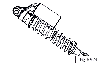
Shock absorber
- Inspect shock absorber for damaged canister, spring coil breakage, weak or hard action of shock absorber. Replace if found.
- Inspect mounting hole rubber inserts for any tear or damage. Replace shock absorber.
- Inspect and replace shock absorber rod if it has any bends, cracks or rusting.
Swingarm
- Inspect LH and RH swingarm for any damages or bends.
- Inspect swingarm in fully assembled condition in motorcycle for side play, sticky movement in working area and replace swingarm if any of these conditions are present.
- Inspect if swingarm end cup is worn-out or damaged.
- Inspect spindle for any wear-out.
Top Yoke
- Inspect top yoke for any cracks or damages in seating area. Replace if damaged.
Replace
- Replace oil seals, dust seals, washers, chain guides whenever removed from the front fork/swingarm.
- Always fill up front fork with recommended oil from a new container. DO NOT reuse the oil.
Assembly
Swingarm
CAUTION Ensure the motorcycle is upright on a firm and flat surface.
- Locate rubber chain strap (a) on the LH side, align mounting holes and tighten with 2 Nos. Hex socket button head bolts (M6) (b).
- Locate bearing sleeve (a) into swingarm LH and RH.
- Assemble end cup (a) into swingarm LH and RH.
- Insert drive chain (a) into swingarm (b) LH.
- Locate and align chain guard front mounting hole on swingarm RH (b) and tighten with Hex socket button head bolt (M6) (a).
- Ensure rear chain guard (a) mounting holes are aligned on the swingarm RH and tighten with 2 Nos. Hex socket button bolts (M6) (b).
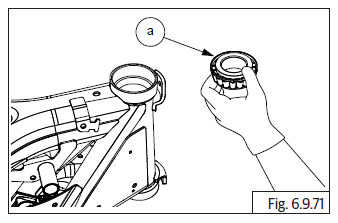
- Assemble end cap (a) with slots facing outside on swingarm RH (b).
- Position swingarm assembly (a) into frame and ensure mounting holes are aligned properly.
- Insert spindle (a) from LH till it is located on the end cap with slots. Do not insert fully
- Insert special tool (a) into slot in frame in RH side, ensuring adjuster swingarm is located correctly and tighten into frame (anticlockwise direction).
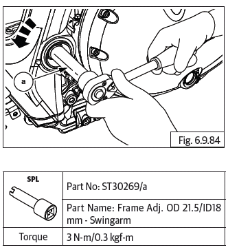
CAUTION Adjuster has left hand threads. Turn anticlockwise to tighten.
- Remove special tool and insert spindle into swingarm completely.
- Locate Hex nut (M16) (a) along with washer (b) on spindle.
- Hold spindle from LH side suitably and tighten nut just sufficiently. DO NOT TIGHTEN NUT FULLY.
Shock Absorber
CAUTION Ensure the motorcycle is upright on a firm and flat surface.
- Locate and align the shock absorber top (a) to mounting hole on frame LH (b) and tighten with button head bolt (M8) (c).
- Locate grab handle into frame (d).
- Align bottom mounting hole of shock absorber (a) to swingarm bracket LH (b) and tighten with button head bolt (M8) (c).
- Tighten both mounting bolts evenly to torque.
- Locate and align the shock absorber top (a) to the mounting hole on frame RH (b) and tighten with button head bolt (M8) (c).
- Align the shock absorber (a) bottom mounting hole to the swingarm bracket RH (b) and tighten with button head bolt (M8) (c).
See also:
 Royal Enfield Interceptor 650 - Service manual > Front Fork Sub Assembly LH and RH
CAUTION The top cap nut is under pressure from the fork spring. Remove cap nut carefully and slowly while unscrewing from main tube. Loosen and remove cap nut (M14) (a) along with O-ring from upper end of front fork leg (b). Remove plate (a). Gently pull out the spacer tube (a). Gently invert fork assembly (a) into a clean tray to collect the fork oil coming out of main tube.
Royal Enfield Interceptor 650 - Service manual > Steering Stem Assembly into Frame Head Tube
Insert the dust seal (a) and roller bearing (b). Assemble bearing (a) with special tool (b).
 Rider's Manual BMW R 1250 GS GSA
 Owner's Manual Harley-Davidson Sportster XL1200X Forty-Eight
 Owner's Manual Honda CBR650R
 Service manual Honda CBR650
 Owner's Manual Honda PCX125
 Owner's Manual Kawasaki Z1000SX
 Service manual Kawasaki Z1000SX
 Owner's Manual Lexmoto Echo
 Owner's Manual Royal Enfield Interceptor 650
 Service manual Royal Enfield Interceptor 650
 Owner's Manual Yamaha MT-07