 Honda CBR650 - Service manual > Fork
REMOVAL (CBR650F/FA)
Remove the following:
- Front wheel
- Front fender
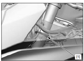
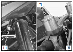
Remove the wire band [1] from the left fork pipe.
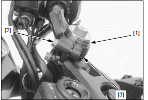
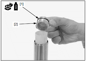
Remove the stopper ring [1].
Keep the reservoir upright to prevent air from entering the hydraulic system.
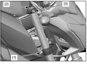
Loosen the pinch bolt [2] and remove the handlebar [3] from the fork tube.
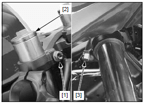
Loosen the top bridge pinch bolt [1].
When the fork is ready to be disassembled, loosen the fork cap [2], but do not remove it.
Support the fork leg securely.
Loosen the bottom bridge pinch bolt [3] and pull the fork leg down, then remove it out of the top and bottom bridges.
INSTALLATION (CBR650F/FA)
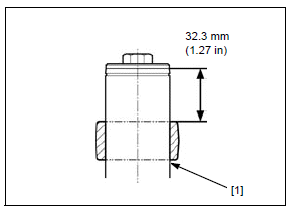
Mark the fork tube at the specified height indicated below, using a marker.
Insert the fork leg [1] into the bottom and top bridges so the fork tube height from the top bridge is specified value (at the mark), then temporarily tighten the pinch bolts.
- Top bridge upper surface-to-fork tube end; 32.3 mm (1.27 in)
Tighten the bottom bridge pinch bolt [1] to the specified torque.
TORQUE: 42 N*m (4.3 kgf*m, 31 lbf*ft)
Tighten the fork cap [2] to the specified torque if it was removed.
TORQUE: 22 N*m (2.2 kgf*m, 16 lbf*ft)
Tighten the top bridge pinch bolt [3] to the specified torque.
TORQUE: 22 N*m (2.2 kgf*m, 16 lbf*ft)
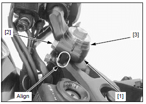
Install the handlebar [1] over the fork tube, aligning the boss with the groove in the top bridge.
Be sure the handlebar holder is fully seated on the top bridge. Push the handlebar forward to touch the boss against the inside of the groove, then tighten the pinch bolt [2] to the specified torque.
TORQUE: 27 N*m (2.8 kgf*m, 20 lbf*ft)
Install the stopper ring [3] into the groove in the fork tube.
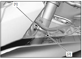
Secure the horn wire [1] to the left fork pipe with the wire band [2].
Install the following:
- Front fender
- Front wheel
REMOVAL (CB650F/FA)
Remove the following:
- Front wheel
- Front fender
- Headlight assembly from the bottom bridge
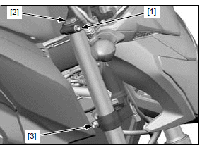
Loosen the top bridge pinch bolt [1].
When the fork is ready to be disassembled, loosen the fork cap [2], but do not remove it.
Support the fork leg securely.
Loosen the bottom bridge pinch bolt [3] and pull the fork leg down, then remove it out of the top and bottom bridges.
INSTALLATION (CB650F/FA)
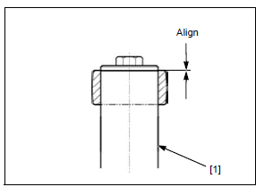
Insert the fork leg [1] into the bottom and top bridges by aligning the upper surface of the fork tube with the top surface of the top bridge, then temporarily tighten the pinch bolts.
Tighten the bottom bridge pinch bolt [1] to the specified torque.
TORQUE: 42 N*m (4.3 kgf*m, 31 lbf*ft)
Tighten the fork cap [2] to the specified torque if it was removed.
TORQUE: 22 N*m (2.2 kgf*m, 16 lbf*ft)
Tighten the top bridge pinch bolt [3] to the specified torque.
TORQUE: 22 N*m (2.2 kgf*m, 16 lbf*ft)
Install the following:
- Front fender
- Front wheel
- Headlight assembly
DISASSEMBLY
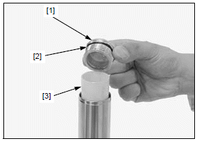
Fork cap is under spring pressure; use care when loosing it.
Remove the following:
- Fork cap [1]
- O-ring [2]
- Spring collar [3]
Remove the fork spring [1].
Pour out the fork fluid by pumping the fork tube up and down several times.
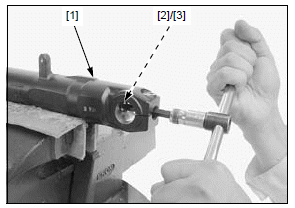
Hold the fork slider [1] in a vise with soft jaws or shop towels.
If the fork piston turns with the socket bolt, temporarily install the fork spring, spring collar and fork cap.
Remove the following:
- Fork socket bolt [2]
- Sealing washer [3]
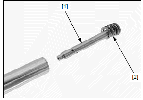
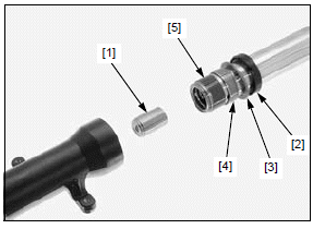
- Fork piston [1]
- Rebound spring [2]
Be careful not to scratch the fork tube.
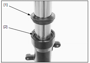
- Dust seal [1]
- Stopper ring [2]
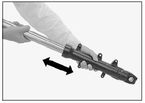
Using quick successive motions, pull the fork tube out of the fork slider.
Remove the following:
- Oil lock piece [1]
- Oil seal [2]
- Back-up ring [3]
- Guide bushing [4]
Do not remove the fork tube bushing, unless it is necessary to replace with a new one.
Carefully remove the fork tube bushing [5] by prying the slit with a flat blade screwdriver until the bushing can be pulled off by hand.
INSPECTION
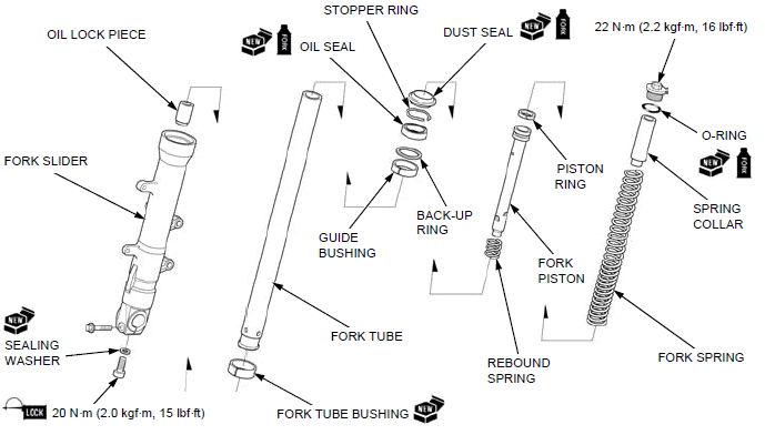
Inspect the following parts for damage, abnormal wear, bend, deformation, scoring and teflon coating wear.
- Fork tube
- Fork slider
- Fork spring
- Rebound spring
- Piston ring
- Fork piston
- Oil lock piece
- Guide bushing
- Fork tube bushing
- Back-up ring
Measure each part according to FRONT WHEEL/ SUSPENSION/STEERING SPECIFICATIONS.
Replace any part if it is out of service limit.
ASSEMBLY
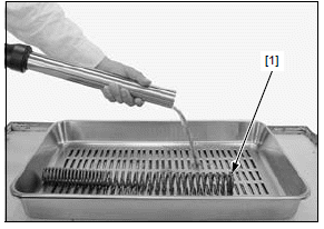
Before assembly, wash all parts with a high flash point or non-flammable solvent and wipe them off completely.
Be careful not to damage the coating on the bushing. Do not spread open the bushing more than necessary.
Install a new fork tube bushing [1] if it has been removed.
NOTE:
- Remove the burrs from the bushing mating surface, being careful not to peel off the coating.
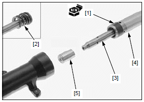
Install the following:
- Rebound spring [2] (onto the fork piston)
- Fork piston [3] (into the fork tube [4] )
- Oil lock piece [5] (onto the fork piston)
Install the fork tube into the fork slider.
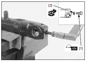
Hold the fork slider in a vise with soft jaws or shop towels.
Apply locking agent to the threads of the fork socket bolt [1].
If the fork piston turns with the socket bolt, temporarily install the fork spring, spring collar and fork cap.
Install the socket bolt with a new sealing washer [2] and tighten it to the specified torque.
TORQUE: 20 N*m (2.0 kgf*m, 15 lbf*ft)
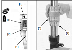
Place the guide bushing [1] over the fork tube and rest it on the slider. Put the back-up ring [2] and an old bushing or equivalent tool on the guide bushing.
Drive the bushing into place, using the special tools.
TOOLS:
[3] Fork seal driver 07947-KA50100
[4] Fork seal driver attachment 07947-KF00100
Wrap vinyl tape around the fork tube top end to avoid damaging the oil seal lip.
Apply fork fluid to the lips of a new oil seal [5] and install it with the marking facing up.
Drive the oil seal until the stopper ring groove [6] is visible using the same tools.
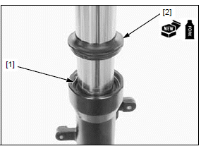
Be careful not to scratch the fork tube.
Install the stopper ring [1] into the groove in the fork slider.
Apply fork fluid to the lips of a new dust seal [2] and install it.
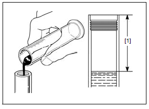
Pour the specified amount of recommended fork fluid into the fork tube.
RECOMMENDED FORK FLUID:
Honda Ultra Cushion Oil 10W or equivalent
FORK FLUID CAPACITY:
CBR650F/FA: 505 +- 2.5 cm3
(17.1 +- 0.08 US oz, 17.8 +- 0.09 Imp oz)
CB650F/FA: 482 +- 2.5 cm3
(16.3 +- 0.08 US oz, 17.0 +- 0.09 Imp oz)
Slowly pump the fork tube several times to remove any trapped air from the lower portion of the fork tube.
Compress the fork tube fully and measure the fluid level [1] from the top end of the fork tube.
[1] FLUID LEVEL:
CBR650F/FA: 140 mm (5.5 in)
CB650F/FA: 128 mm (5.0 in)
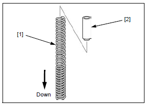
Pull the fork pipe up and install the fork spring [1] with the tightly wound coil side facing down.
Install the spring collar [2] with the stepped side facing down.
Coat a new O-ring [1] with fork fluid and install it into the groove in the fork cap [2].
Tighten the fork cap after installing the fork tube into the fork bridges.
Install the fork cap into the fork tube.
See also:
 Honda CBR650 - Service manual > Front wheel
REMOVAL/INSTALLATION NOTE: Do not operate the brake lever after removing the wheel. Remove the right and left front brake calipers. Remove the axle bolt [1] and loosen the right [2] and left [3] axle pinch bolts.
Honda CBR650 - Service manual > Steering stem
REMOVAL CBR650F/FA: Remove the following: Middle cowls Horn Disconnect the ignition switch 2P (Brown) connector [1] and immobilizer receiver 4P (Black) connector [2].
 Rider's Manual BMW R 1250 GS GSA
 Owner's Manual Harley-Davidson Sportster XL1200X Forty-Eight
 Owner's Manual Honda CBR650R
 Service manual Honda CBR650
 Owner's Manual Honda PCX125
 Owner's Manual Kawasaki Z1000SX
 Service manual Kawasaki Z1000SX
 Owner's Manual Lexmoto Echo
 Owner's Manual Royal Enfield Interceptor 650
 Service manual Royal Enfield Interceptor 650
 Owner's Manual Yamaha MT-07