 Honda CBR650 - Service manual > Fuel gauge/fuel level sensor
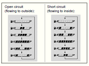
FUEL GAUGE INSPECTION
When the circuit malfunction occurs, the combination meter displays the flow pattern in the fuel gauge. If it is indicated, check for open or short circuit in the following wire between the combination meter and fuel pump unit.
- CBR650F/FA: Pink wires
- CB650F/FA: Black or Pink wire
If the above wire is OK, check the fuel level sensor.
If the fuel level sensor is OK, replace the combination meter.
- CBR650F/FA
- CB650F/FA
FUEL LEVEL SENSOR INSPECTION
Remove the fuel pump unit.
Measure the resistance between the fuel pump unit 3P (Black) connector [1] terminals.
CONNECTION: Red/black - Black/white
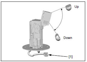
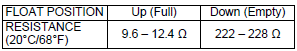
If the resistance is out of specification, replace the fuel level sensor.
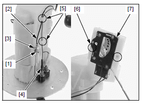
REMOVAL/INSTALLATION
Remove the fuel pump unit.
Remove the screw [1], Black wire terminal [2] and stopper [3].
Disconnect the Pink wire connector [4].
Release the wires from the guides [5] of the fuel pump unit.
Press the tabs [6] and remove the fuel level sensor assembly [7] from the fuel pump unit.
Installation is in the reverse order of the removal.
- When installing the fuel level sensor assembly, slide it until tabs lock with a "CLICK".
See also:
 Honda CBR650 - Service manual > High coolant temperature indicator/ECT sensor, engine oil pressure
indicator/EOP switch
Honda CBR650 - Service manual > High coolant temperature indicator/ECT sensor, engine oil pressure
indicator/EOP switch
High coolant temperature indicator/ECT sensor SYSTEM INSPECTION NOTE: If the high coolant temperature indicator and digital display do not function at all, refer to combination meter initial operation check.
Honda CBR650 - Service manual > Switches
Ignition switch INSPECTION Remove the following: Left middle cowl (CBR650F/FA) Headlight assembly from the bottom bridge (CB650F/FA)
 Rider's Manual BMW R 1250 GS GSA
 Owner's Manual Harley-Davidson Sportster XL1200X Forty-Eight
 Owner's Manual Honda CBR650R
 Service manual Honda CBR650
 Owner's Manual Honda PCX125
 Owner's Manual Kawasaki Z1000SX
 Service manual Kawasaki Z1000SX
 Owner's Manual Lexmoto Echo
 Owner's Manual Royal Enfield Interceptor 650
 Service manual Royal Enfield Interceptor 650
 Owner's Manual Yamaha MT-07