 Honda CBR650 - Service manual > Switches
Ignition switch
INSPECTION
Remove the following:
- Left middle cowl (CBR650F/FA)
- Headlight assembly from the bottom bridge (CB650F/FA)
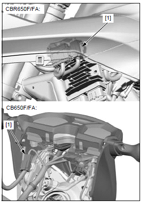
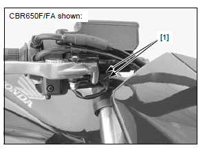
Disconnect the ignition switch 2P (Brown) connector [1].
Check for continuity between the switch side 2P (Brown) connector terminals in each switch position according to the continuity chart.
- CBR650F/FA
- CB650F/FA
REMOVAL/INSTALLATION
Remove the top bridge.
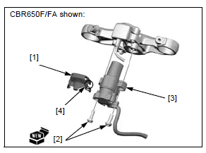
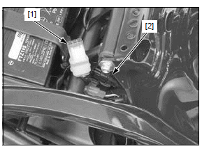
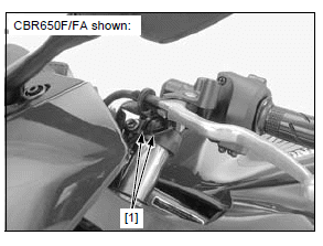
Remove the protector [1].
Remove the two bolts [2] and ignition switch [3].
NOTE:
- Use a drill or an equivalent tool when removing the ignition switch mounting bolts.
Installation is in the reverse order of removal.
NOTE:
- Replace the switch bolts with new ones.
- Route the immobilizer receiver wire into the left groove [4] in the protector.
TORQUE:
Ignition switch mounting bolt:
24 N*m (2.4 kgf*m, 18 lbf*ft)
Install the top bridge.
Handlebar switch
LEFT HANDLEBAR SWITCH
Remove the following:
- Left middle cowl (CBR650F/FA)
- Left tank shroud A (CB650F/FA)
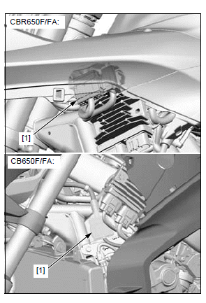
Disconnect the left handlebar switch 10P (Gray) connector [1].
Check for continuity between the switch side 10P (Gray) connector terminals in each switch position according to the continuity chart.
- CBR650F/FA
- CB650F/FA
RIGHT HANDLEBAR SWITCH
Remove the following:
- Right middle cowl (CBR650F/FA)
- Right tank shroud A (CB650F/FA)
Disconnect the right handlebar switch 8P (Blue) connector [1].
Check for continuity between the switch side 8P (Blue) connector terminals in each switch position according to the continuity chart.
- CBR650F/FA
- CB650F/FA
Brake light switch
FRONT
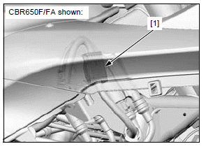
Disconnect the brake light switch connectors [1] and check for continuity between the switch terminals.
There should be continuity with the brake lever squeezed, and no continuity when the brake lever is released.
REAR
Remove the seat.
Release the optional 6P connector [1] from the stay and disconnect the rear brake light switch 2P (Black) connector [2].
Check for continuity between the switch side connector terminals.
There should be continuity with the brake pedal depressed, and no continuity when the brake pedal is released.
Clutch switch
Disconnect the clutch switch connectors [1] and check for continuity between the switch terminals.
There should be continuity with the clutch lever squeezed, and no continuity when the clutch lever is released.
Neutral switch
INSPECTION
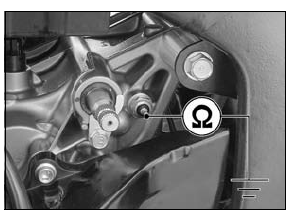
Disconnect the neutral switch wire.
Check for continuity between the switch terminal and engine ground.
There should be continuity with the transmission in neutral, and no continuity when the transmission is in gear except neutral.
REMOVAL/INSTALLATION
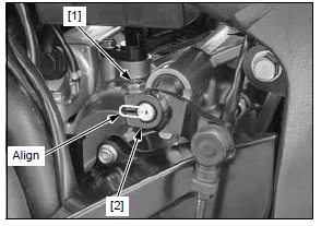
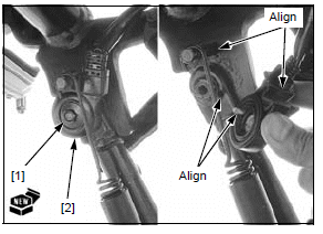
Remove the pinch bolt [1].
Release the gearshift arm [2] from the gearshift spindle.
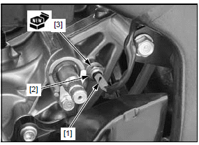
Disconnect the neutral switch 1P (White) connector [1].
Remove the neutral switch [2] and sealing washer [3].
Installation is in the reverse order of removal.
NOTE:
- Replace the sealing washer with a new one.
- Align the slit in the gearshift arm with the punch mark on the spindle.
TORQUE:
Neutral switch: 12 N*m (1.2 kgf*m, 9 lbf*ft)
Sidestand switch
INSPECTION
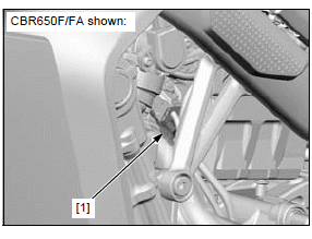
Disconnect the sidestand switch 2P (Black) connector [1].
Check for continuity between the switch side connector terminals.
There should be continuity with the sidestand retracted, and, no continuity when the sidestand is lowered.
REMOVAL/INSTALLATION
Remove the drive sprocket cover.
Disconnect the sidestand switch 2P (Black) connector [1] and remove the sidestand switch wire [2] out of the frame.
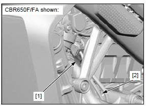
Remove the bolt [1] and sidestand switch [2].
Installation is in the reverse order of removal.
NOTE:
- Align the switch pin with the hole in the sidestand and the switch groove with the return spring pin.
- Replace the switch bolt with a new one.
TORQUE:
Sidestand switch mounting bolt:
10 N*m (1.0 kgf*m, 7 lbf*ft)
See also:
 Honda CBR650 - Service manual > Fuel gauge/fuel level sensor
FUEL GAUGE INSPECTION When the circuit malfunction occurs, the combination meter displays the flow pattern in the fuel gauge. If it is indicated, check for open or short circuit in the following wire between the combination meter and fuel pump unit. CBR650F/FA: Pink wires CB650F/FA: Black or Pink wire
Honda CBR650 - Service manual > Horn
INSPECTION Remove the tank shroud A (CB650F/FA only). Disconnect the connectors [1] from the horn. Connect a 12 V battery to the horn terminals. The horn is normal if it sounds when the 12 V battery is connected across the horn terminals.
 Rider's Manual BMW R 1250 GS GSA
 Owner's Manual Harley-Davidson Sportster XL1200X Forty-Eight
 Owner's Manual Honda CBR650R
 Service manual Honda CBR650
 Owner's Manual Honda PCX125
 Owner's Manual Kawasaki Z1000SX
 Service manual Kawasaki Z1000SX
 Owner's Manual Lexmoto Echo
 Owner's Manual Royal Enfield Interceptor 650
 Service manual Royal Enfield Interceptor 650
 Owner's Manual Yamaha MT-07