 Kawasaki Z1000SX - Service manual > Fuel Injectors
Fuel Injector Removal/Installation
- Refer to the Throttle Body Assy Disassembly/Assembly.
Fuel Injector Audible Inspection
NOTE
- Be sure the battery is fully charged.
- Remove the lower side fairing (see Lower Side Fairing Removal in the Frame chapter).
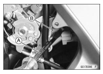
- Start the engine, and let it idle.
- Apply the tip of a screwdriver [A] to the fuel injector [B].
Put the grip end onto your ear, and listen whether the fuel injector is clicking or not.
- A sound scope can also be used.
- The click interval becomes shorter as the engine speed rises.
- Do the same for the other fuel injectors.
If all the fuel injectors click at a regular intervals, the fuel injectors are normal.
- Turn the ignition switch OFF.
If any fuel injector does not click, check the fuel injector resistance (see Fuel Injector Resistance Inspection).
Fuel Injector Resistance Inspection
- Remove the throttle body assy with the connectors installed (see Throttle Body Assy Removal).
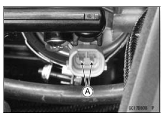
- Disconnect the injector connector.
- Connect a digital meter to the terminals [A] of the injector.
- Measure the fuel injector resistance.
Fuel Injector Resistance
Connections:
For Fuel Injector #1
W/R ←→ BL/R terminal
For Fuel Injector #2
W/R ←→ BL/O terminal
For Fuel Injector #3
W/R ←→ BL/W terminal
For Fuel Injector #4
W/R ←→ BL/Y terminal
Standard: About 11.7 - 12.3 Ω at 20ºC (68ºF)
If the reading is out of the standard, replace the injector.
Fuel Injector Power Source Voltage Inspection
NOTE
- Be sure the battery is fully charged.
- Remove the air cleaner housing (see Air Cleaner Housing Removal).
- Turn the ignition switch OFF.
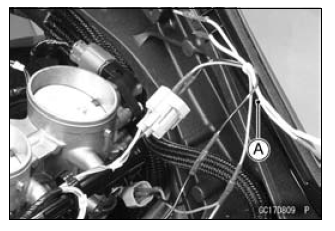
- Disconnect the injector connector and connect the harness adapter [A]
between these connectors as shown.
Main Harness [B]
Fuel Injector #1 [C]
Special Tool - Measuring Adapter: 57001-1700
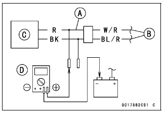
- Connect a digital meter [D] to the harness adapter lead.
Fuel Injector Power Source Voltage
Connections to Adapter:
For Fuel Injector #1, #2, #3, #4
Digital Meter (+) → R (injector W/R) lead
Digital Meter (-) → Battery (-) terminal
- Measure the power source voltage with the engine stopped.
- Turn the engine stop switch to run position.
- Turn the ignition switch ON.
Power Source Voltage
Standard: Battery Voltage for 3 seconds, and then 0 V
- Turn the ignition switch OFF.
If the reading is not the standard, check the ECU main relay and fuel pump relay (see Relay Circuit Inspection in the Electrical System chapter).
If the main relay and pump relay are normal, check the wiring (see Fuel Injector Circuit).
If the wiring is good, check the ECU for its ground and power supply (see ECU Power Supply Inspection).
If the ground and power supply are good, replace the ECU (see ECU Removal/Installation).
Fuel Injector Output Voltage Inspection
NOTE
- Be sure the battery is fully charged.
- Turn the ignition switch OFF.
- Remove the ECU (see ECU Removal).
- Do not disconnect the ECU connector.
- Connect the relay box connectors.
- Connect a digital meter [A] to the connectors [B] with the needle adapter set.
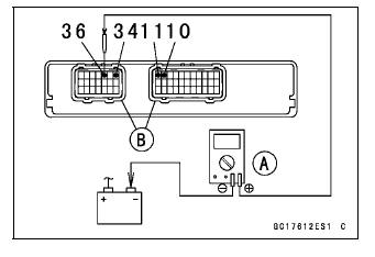
Special Tool - Needle Adapter Set: 57001-1457
Fuel Injector Output Voltage
Connections to ECU Connector:
For Fuel Injector #1
Digital Meter (+) → BL/R lead (ECU terminal 36)
Digital Meter (-) → Battery (-) terminal
For Fuel Injector #2
Digital Meter (+) → BL/O lead (ECU terminal 34)
Digital Meter (-) → Battery (-) terminal
For Fuel Injector #3
Digital Meter (+) → BL/W lead (ECU terminal 11)
Digital Meter (-) → Battery (-) terminal
For Fuel Injector #4
Digital Meter (+) → BL/Y lead (ECU terminal 10)
Digital Meter (-) → Battery (-) terminal
- Measure the output voltage with the engine stopped and with the connector joined.
- Turn the engine stop switch to run position.
- Turn the ignition switch ON.
Output Voltage
Standard: Battery Voltage for 3 seconds, and then 0 V
- Turn the ignition switch OFF.
If the reading is not the standard, check the ECU main relay and fuel pump relay (see Relay Circuit Inspection in the Electrical System chapter).
If the main relay and pump relay are normal, check the wiring (see Fuel Injector Circuit).
If the wiring is good, check the ECU for its ground and power supply (see ECU Power Supply Inspection).
If the ground and power supply are good, replace the ECU (see ECU Removal/Installation).
If there is still no battery voltage, check the fuel injector resistance (see Fuel Injector Resistance Inspection) and wiring (see Fuel Injector Circuit).
Fuel Injector Fuel Line Inspection
- Remove:
Fuel Tank (see Fuel Tank Removal)
Fuel Hose (see Fuel Hose Replacement in the Periodic Maintenance chapter)- Be sure to place a piece of cloth around the fuel outlet pipe of the fuel pump and the delivery pipe of the throttle body assy.
WARNING Fuel is flammable and explosive under certain conditions and can cause severe burns. Be prepared for fuel spillage; any spilled fuel must be completely wiped up immediately. When the fuel hose is disconnected, fuel spills out from the hose and the pipe because of residual pressure. Cover the hose connection with a piece of clean cloth to prevent fuel spillage.
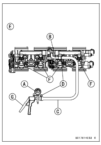
- Check the injector fuel line for leakage as follows.
- Connect a commercially available vacuum/pressure pump [A] to the
nipple of the delivery pipe [B] with the fuel hose [C] (both ends with
the clamps [D]) as shown in the figure.
Lower Side View [E]
- Apply soap and water solution to the areas [F] as shown in the figure.
- Watching the pressure gauge, squeeze the pump lever [G], and build up the pressure until the pressure reaches the maximum pressure.
- Connect a commercially available vacuum/pressure pump [A] to the
nipple of the delivery pipe [B] with the fuel hose [C] (both ends with
the clamps [D]) as shown in the figure.
Injector Fuel Line Maximum Pressure
Standard: 300 kPa (3.06 kgf/cm², 43 psi)
NOTICE During pressure testing, do not exceed the maximum pressure for which the system is designed.
- Watch the gauge for at least 6 seconds.
If the pressure holds steady, the fuel line is good.
If the pressure drops at once or if bubbles are found in the area, the fuel line is leaking. Replace the delivery pipe assy, injectors and related parts.
- Repeat the leak test, and check the fuel line for no leakage.
- Install:
Fuel Hose (see Fuel Hose Replacement in the Periodic Maintenance chapter)
Fuel Tank (see Fuel Tank Installation) - Confirm that the drain hose and clamp are installed securely and run the hose correctly (see Cable, Wire, and Hose Routing section in the Appendix chapter).
- Start the engine and check for fuel leakage.
Fuel Injector Circuit
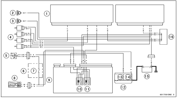
- ECU
- Meter Ground
- Frame Ground
- Fuel Injectors
- Engine Stop Switch
- Fuse Box 2
- Ignition Fuse 15 A
- Ignition Switch
- Relay Box
- ECU Main Relay
- Fuel Pump Relay
- Starter Relay
- FI Fuse 15 A
- Main Fuse 30 A
- Battery 12 V 8 Ah
- Water-proof Joint C
See also:
 Kawasaki Z1000SX - Service manual > Fuel Pump
Fuel Pump Removal WARNING Gasoline is extremely flammable and can be explosive under certain conditions, creating the potential for serious burns. Make sure the area is well-ventilated and free from any source of flame or sparks; this includes any appliance with a pilot light. Do not smoke. Turn the ignition switch OFF.
Kawasaki Z1000SX - Service manual > Throttle Grip and Cables, Throttle Body Assy
Throttle Grip and Cables Free Play Inspection Refer to the Throttle Control System Inspection in the Periodic Maintenance chapter.
 Rider's Manual BMW R 1250 GS GSA
 Owner's Manual Harley-Davidson Sportster XL1200X Forty-Eight
 Owner's Manual Honda CBR650R
 Service manual Honda CBR650
 Owner's Manual Honda PCX125
 Owner's Manual Kawasaki Z1000SX
 Service manual Kawasaki Z1000SX
 Owner's Manual Lexmoto Echo
 Owner's Manual Royal Enfield Interceptor 650
 Service manual Royal Enfield Interceptor 650
 Owner's Manual Yamaha MT-07