 Kawasaki Z1000SX - Service manual > Fuel Pump
Fuel Pump Removal
WARNING Gasoline is extremely flammable and can be explosive under certain conditions, creating the potential for serious burns. Make sure the area is well-ventilated and free from any source of flame or sparks; this includes any appliance with a pilot light. Do not smoke. Turn the ignition switch OFF.
Disconnect the battery (-) terminal. To avoid fuel spills, draw it from the tank when the engine is cold. Be prepared for fuel spillage; any spilled fuel must be completely wiped up immediately.
NOTICE Never drop the fuel pump especially on a hard surface.
Such a shock to the pump can damage it.
- Draw the fuel out from the fuel tank with a commercially available electric pump.
- Remove the fuel tank (see Fuel Tank Removal).
- Be careful of fuel spillage from the fuel tank since fuel still remains in the fuel tank and fuel pump. Plug the fuel pipe of the fuel tank.
- Turn the fuel tank upside down.
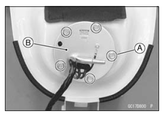
- Remove the fuel pump bolts [A], and take out the fuel pump [B].
NOTICE Do not pull the leads of the fuel pump. If they are pulled, the lead terminals may be damaged.
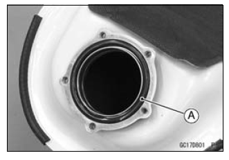
- Discard the fuel pump gasket [A].
Fuel Pump Installation
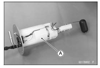
- Remove dirt or dust from the fuel pump [A] by lightly applying compressed air.
- Replace the fuel pump gasket with a new one.
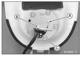
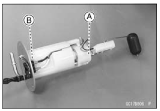
- Check that the fuel pump terminal [A] and band [B] are in place.
- Apply a non-permanent locking agent to the threads of the fuel pump bolts.
- Tighten the fuel pump bolts [C] to a snug fit.
- Tighten the fuel pump bolts alternating diagonally.
Torque - Fuel Pump Bolts: 9.8 N*m (1.0 kgf*m, 87 in*lb)
- Tighten the pump bolts again to check the tightness.
Fuel Pump Operation Inspection
NOTE
- Be sure the battery is fully charged.
- Turn the engine stop switch to run position.
- Turn the ignition switch ON and make sure that the fuel pump operates (make light sounds) for 3 seconds, and then stops.
- Turn the ignition switch OFF.
If the pump does not operate as described above, check the operating voltage (see Fuel Pump Operating Voltage Inspection).
Fuel Pump Operating Voltage Inspection
NOTE
- Be sure the battery is fully charged.
- Turn the ignition switch OFF.
- Remove the front seat (see Front Seat Removal in the Frame chapter).
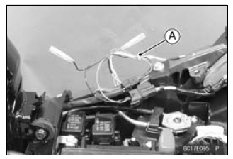
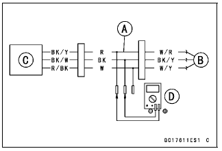
- Disconnect the fuel pump lead connector and connect the harness adapter
[A] between these connectors as shown.
Main Harness [B]
Fuel Pump [C]
Special Tool - Measuring Adapter: 57001-1700
- Connect a digital meter [D] to the harness adapter leads.
Fuel Pump Operating Voltage
Connections to Adapter:
Digital Meter (+) → R (pump BK/Y) lead
Digital Meter (-) → BK (pump BK/W) lead
- Measure the operating voltage with engine stopped and with the connector joined.
- Turn the engine stop switch run position.
- Turn the ignition switch ON.
Operating Voltage
Standard: Battery Voltage for 3 seconds, and then 0 V
- Turn the ignition switch OFF.
If the reading is not the standard, check the ECU main relay and fuel pump relay (see Relay Circuit Inspection in the Electrical System chapter).
If the main relay and pump relay are normal, check the wiring for continuity (see Fuel Pump Circuit).
If the wiring is good, check the ECU for its ground and power supply (see ECU Power Supply Inspection).
If the ground and power supply are good, replace the ECU (see ECU Removal/Installation).
Pressure Regulator Removal
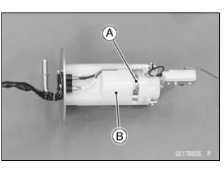
- The pressure regulator [A] is built into the fuel pump [B] and can not be removed.
Pump Screen, Fuel Filter Cleaning
- The pump screen [A] and fuel filter [B] are built into the pump and can not be cleaned or checked.
If the pump screen or fuel filter is suspected of clogging or being damaged, replace it with the fuel pump as a set.
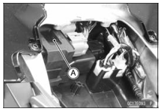
Fuel Pump Relay Removal/Installation
- The fuel pump relay is built in the relay box [A].
- Refer to the Relay Box Removal in the Electrical System chapter.
Fuel Pump Relay Inspection
- Refer to the Relay Circuit Inspection in the Electrical System chapter.
Fuel Pump Circuit
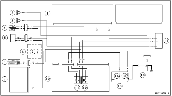
- ECU
- Meter Ground
- Frame Ground
- Engine Stop Switch
- Fuel Pump/Fuel Level Sensor
- Fuse Box 2
- Ignition Fuse 15 A
- Ignition Switch
- Meter Unit
- Relay Box
- ECU Main Relay
- Fuel Pump Relay
- Starter Relay
- FI Fuse 15 A
- Main Fuse 30 A
- Battery 12 V 8 Ah
- Water-proof Joint C
See also:
 Kawasaki Z1000SX - Service manual > Fuel Line
Fuel Pressure Inspection NOTE Be sure the battery is fully charged. Remove: Fuel Hose (see Fuel Hose Replacement in the Periodic Maintenance chapter) Support the fuel tank with a suitable bar (see Fuel Tank Removal in the Fuel System (DFI) chapter). Be sure to place a piece of cloth around the fuel outlet pipe of the fuel pump and the delivery pipe of the throttle body assy.
Kawasaki Z1000SX - Service manual > Fuel Injectors
Fuel Injector Removal/Installation Refer to the Throttle Body Assy Disassembly/Assembly. Fuel Injector Audible Inspection
 Rider's Manual BMW R 1250 GS GSA
 Owner's Manual Harley-Davidson Sportster XL1200X Forty-Eight
 Owner's Manual Honda CBR650R
 Service manual Honda CBR650
 Owner's Manual Honda PCX125
 Owner's Manual Kawasaki Z1000SX
 Service manual Kawasaki Z1000SX
 Owner's Manual Lexmoto Echo
 Owner's Manual Royal Enfield Interceptor 650
 Service manual Royal Enfield Interceptor 650
 Owner's Manual Yamaha MT-07