 Kawasaki Z1000SX - Service manual > Fuel System (DFI)
Throttle Control System Inspection
- Check that the throttle grip [A] moves smoothly from full open to close, and the throttle closes quickly and completely by the return spring in all steering positions.
If the throttle grip does not return properly, check the throttle cable routing, grip free play, and cable damage. Then lubricate the throttle cable.
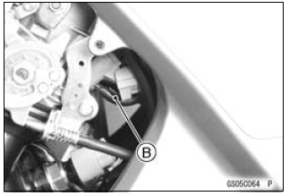
- Check the throttle grip free play [B].
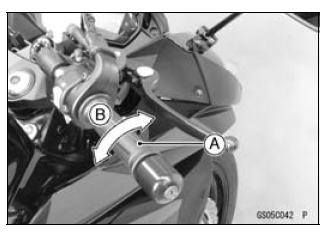
Throttle Grip Free Play
Standard: 2 - 3 mm (0.08 - 0.12 in.)
If the free play is incorrect, adjust the throttle cable as follows.
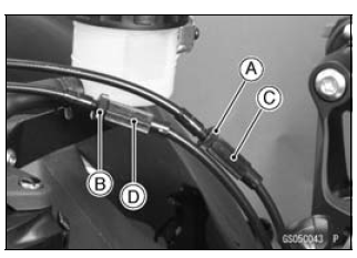
- Loosen the locknuts [A] [B].
- Screw both throttle cable adjusters [C] [D] to give the throttle grip plenty of play.
- Turn the decelerator cable adjuster [C] until 2 - 3 mm (0.08 - 0.12 in.) of throttle grip play is obtained.
- Tighten the locknut [A].
- Turn the accelerator cable adjuster [D] until 2 - 3 mm (0.08 - 0.12 in.) of throttle grip play is obtained.
- Tighten the locknut [B].
If the free play can not be adjusted with the adjusters, replace the cable.
Engine Vacuum Synchronization Inspection
NOTE
- These procedures are explained on the assumption that the intake and exhaust systems of the engine are in good condition.
- Situate the motorcycle so that it is vertical.
- Remove the air cleaner housing (see Air Cleaner Housing Removal in the Fuel System (DFI) chapter).
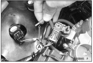
- Pull off the rubber caps [A] and vacuum hose [B] from the fittings of each throttle body.
- For the California and Southeast Asia Models, pull off the vacuum hose [A].
- Plug the vacuum hose end [A].
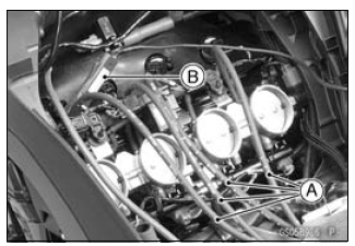
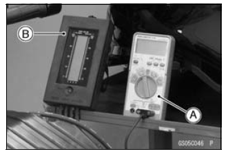
- Connect a vacuum gauge (special tool) and hoses [A] to the fittings on the throttle body.
Special Tool - Vacuum Gauge: 57001-1369
- Connect a highly accurate tachometer [B] to one of the stick coil primary leads.
- Plug the air switching valve hose end [A] and air cleaner housing fitting [B].
- Install the air cleaner housing (see Air Cleaner Housing Installation in the Fuel System (DFI) chapter).
- Remove the fuel hose (see Fuel Hose Replacement).
- Connect the following parts temporary.
Fuel Pump Lead Connector [A]
Fuel Hose [B]
Special Tool - Fuel Hose: 57001-1607
- Start the engine and warm it up thoroughly.
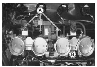
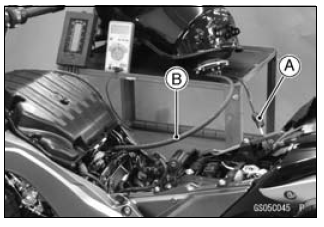
- Check the idle speed, using a highly accurate tachometer [A].
Idle Speed
Standard: 1 100 +-50 r/min (rpm)
If the idle speed is out of the specified range, adjust it with the adjusting screw (see Idle Speed Adjustment).
NOTICE Do not measure the idle speed by the tachometer of the meter unit.
- While idling the engine, inspect the throttle body vacuum, using the vacuum gauge [B].
Throttle Body Vacuum
Standard: 40.7 +-1.3 kPa (305 +-10 mmHg) at idle speed
If any vacuum is not within specifications, first synchronize the balance of the left (#1, #2 throttle valves) and right (#3, #4 throttle valves) assemblies.
Example:
#1: 260 mmHg
#2: 300 mmHg
#3: 250 mmHg
#4: 280 mmHg
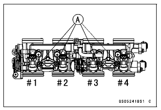
- With the engine at the correct idle speed, equalize higher vacuum of #1 or #2 (for example 300 mmHg) to higher vacuum of #3 or #4 (for example 280 mmHg) by turning the center adjusting screw [A].
NOTE
- After adjustment, the final vacuum measurement between the highest throttle valves may not be 290 mmHg (for example). The goal is to have the highest two vacuums between the left (#1 and #2) and right (#3 and #4) banks be the same.
- Open and close the throttle after each measurement, and adjust the idle speed as necessary.
- Once the throttle valves have been synchronized, inspect output voltage of the main throttle sensor to ensure proper operation (procedure is explained at the end of this section).
If any one vacuum measurement is out of the specified range after left (#1, #2) and right (#2, #3) synchronization, adjust the bypass screws [A].
Special Tool - Pilot Screw Adjuster, A [B]: 57001-1239
- Adjust the lower vacuum between #1 and #2 to the higher vacuum of #1 and #2.
- Adjust the lower vacuum between #3 and #4 to the higher vacuum of #3 and #4.
- Open and close the throttle valves after each measurement, and adjust the idle speed as necessary.
- Check the vacuums as before.
If all vacuums are within the specification range, finish the engine vacuum synchronization.
If any vacuum can not be adjusted within the specification, remove the bypass screws #1 - #4 and clean them.
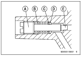
- Turn in the bypass screw [A] with counting the number of turns until it seals fully but not tightly. Record the number of turns.
NOTICE Do not over tighten them. They could be damaged, requiring replacement.
- Remove:
Bypass Screw
Spring [B]
Washer [C]
O-ring [D] - Check the bypass screw and its hole for carbon deposits.
If any carbons accumulate, wipe the carbons off from the bypass screw and the hole, using a cotton pad penetrated with a high-flash point solvent.
- Replace the O-ring with a new one.
- Check the tapered portion [E] of the bypass screw for wear or damage.
If the bypass screw is worn or damaged, replace it.
- Turn in the bypass screw until it seats fully but not tightly.
- Back out the same number of turns counted when first turned in. This is to set the screw to its original position.
NOTE
- A throttle body has different "turns out" of the bypass screw for each individual unit. On setting the bypass screw, use the "turns out" determined during disassembly.
- Repeat the same procedure for other bypass screws.
- Repeat the synchronization.
If the vacuums are correct, check the output voltage of the main throttle sensor (see Main Throttle Sensor Output Voltage Inspection in the Fuel System (DFI) chapter).
Special Tool - Throttle Sensor Setting Adapter: 57001 -1538
Main Throttle Sensor Output Voltage
Connections to Adapter:
Digital Meter (+) → W (sensor BL/W) lead
Digital Meter (-) → BK (sensor BR/BK) lead
Standard: DC 0.985 - 1.015 V at idle throttle opening
If the output voltage is out of the standard, check the input voltage of the main throttle sensor (see Main Throttle Sensor Input Voltage Inspection in the Fuel System (DFI) chapter).
- Remove the vacuum gauge hoses and install the rubber caps on the original position.
- For the California and Southeast Asia Models, install the vacuum hoses.
- Run the vacuum hoses according to Cable, Wire, and Hose Routing section in the Appendix chapter. Refer to the diagram of the evaporative emission control system in the Fuel System (DFI) chapter too.
Idle Speed Inspection
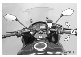
- Start the engine and warm it up thoroughly.
- With the engine idling, turn the handlebar to both sides [A].
If handlebar movement changes the idle speed, the throttle cables may be improperly adjusted or incorrectly routed or damaged. Be sure to correct any of these conditions before riding (see Throttle Control System Inspection and Cable, Wire, and Hose Routing section in the Appendix chapter).
WARNING Operation with improperly adjusted, incorrectly routed or damaged cables could result in an unsafe riding condition. Follow the service manual to be make sure to correct any of these conditions.
- Check the idle speed.
Idle Speed
Standard: 1 100 +-50 r/min (rpm)
If the idle speed is out of the specified range, adjust it.
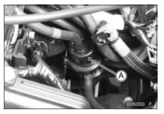
Idle Speed Adjustment
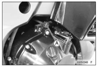
- Start the engine and warm it up thoroughly.
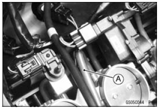
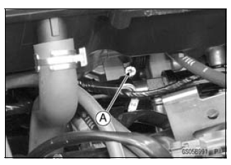
- Turn the adjusting screw [A] until the idle speed is correct.
- Open and close the throttle a few times to make sure that the idle speed is within the specified range. Readjust if necessary.
Fuel Hose Inspection (fuel leak, damage, installation condition)
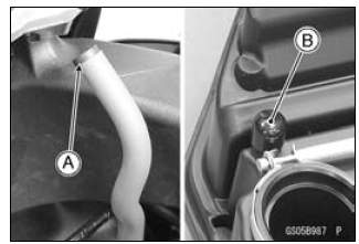
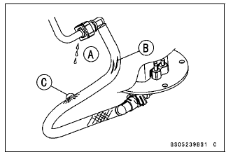
- If the motorcycle is not properly handled, the high pressure inside the fuel line can cause fuel to leak [A] or the hose to burst. Support the fuel tank with a suitable bar (see Fuel Hose Replacement) and check the fuel hoses.
Replace the hose if any fraying, cracks [B] or bulges [C] are noticed.
- Check that the hoses are routed according to Cable, Wire, and Hose Routing section in the Appendix chapter.
Replace the hose if it has been sharply bent or kinked.
Hose Joints [A]
Fuel Hose [B]
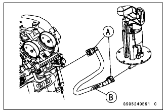
- Check that the hose joints are securely connected.
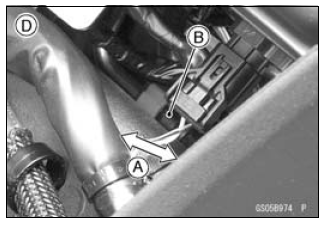
- Push and pull [A] the hose joint [B] back and forth more than two
times, and make sure it is locked and does not come off.
Fuel Pump Side [C]
Throttle Body Assy Side [D]
- Push and pull [A] the hose joint [B] back and forth more than two
times, and make sure it is locked and does not come off.
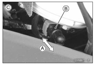
WARNING Leaking fuel can cause a fire or explosion resulting in serious burns. Make sure the hose joint is installed correctly on the delivery pipe.
If it comes off, reinstall the hose joint.
Evaporative Emission Control System (CAL and SEA-B1 Models) Inspection
- Inspect the canister as follows.
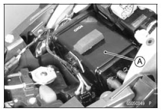
- Remove the front seat (see Front Seat Removal in the Frame chapter).
- Remove the canister [A], and disconnect the hoses from the canister.
- Visually inspect the canister for cracks or other damage.
If the canister has any cracks or bad damage, replace it with a new one.
NOTE
- The canister is designed to work well through the motorcycle's life without any maintenance if it is used under normal conditions.
- Check the liquid/vapor separator as follows.
- Lift up the fuel tank front side, and support the fuel tank with the suitable bar (see Fuel Hose Replacement).
- Disconnect the hoses from the separator, and remove the separator [A] from the motorcycle right side.
- Visually inspect the separator for cracks and other damage.
If the separator has any cracks or damage, replace it with a new one.
- To prevent the gasoline from flowing into or out of the canister, hold the separator perpendicular to the ground.
- Check the hoses of the evaporative emission control system as follows.
- Check that the hoses are securely connected and clips are in position.
- Replace any kinked, deteriorated or damaged hoses.
- Run the hoses according to Cable, Wire, and Hose Routing section in the Appendix chapter. Refer to the diagram of the evaporative emission control system in the Fuel System (DFI) chapter too.
- When installing the hoses, avoid sharp bending, kinking, flattening or twisting, and route the hoses with a minimum of bending so that the emission flow will not be obstructed.
See also:
 Kawasaki Z1000SX - Service manual > Cooling System
Coolant Level Inspection NOTE Check the level when the engine is cold (room or ambient temperature). Check the coolant level in the reserve tank [A] with the motorcycle held perpendicular (Do not use the sidestand).
 Rider's Manual BMW R 1250 GS GSA
 Owner's Manual Harley-Davidson Sportster XL1200X Forty-Eight
 Owner's Manual Honda CBR650R
 Service manual Honda CBR650
 Owner's Manual Honda PCX125
 Owner's Manual Kawasaki Z1000SX
 Service manual Kawasaki Z1000SX
 Owner's Manual Lexmoto Echo
 Owner's Manual Royal Enfield Interceptor 650
 Service manual Royal Enfield Interceptor 650
 Owner's Manual Yamaha MT-07