 Honda CBR650 - Service manual > Fuel tank
REMOVAL/INSTALLATION
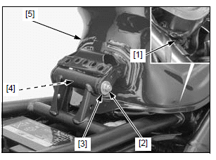
Disconnect the quick connect fitting from the fuel tank.
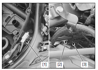
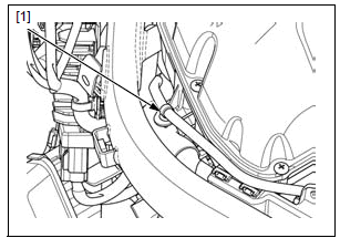
Release the wire clip [1] from the rear fender B.
Lower the fuel tank, being careful not to pinch the wire and hoses.
Remove the nut [2], washer [3], bolt [4] and fuel tank [5].
Installation is in the reverse order of removal.
NOTE:
- The mounting bolt is installed from the left side.
TORQUE:
Fuel tank mounting nut: 12 N*m (1.2 kgf*m, 9 lbf*ft)
Connect the quick connect fitting.
Fuel pump unit
INSPECTION
Turn the ignition switch ON with the engine stop switch " "
and confirm that the fuel pump operates for 2 seconds.
"
and confirm that the fuel pump operates for 2 seconds.
If the fuel pump does not operate, inspect as follows: Turn the ignition switch OFF.
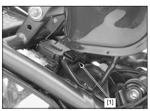
Lift the fuel tank and support it.
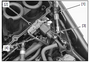
Disconnect the fuel pump 3P (Black) connector [1].
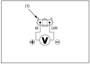
Turn the ignition switch ON with the engine stop switch "".
Measure the voltage between the terminals of the wire harness side fuel pump 3P (Black) connector [1].
CONNECTION: Black (+) - Green/red (-)
There should be battery voltage for 2 seconds.
If there is battery voltage, replace the fuel pump unit.
If there is no voltage, inspect the following:
- Green/red wire between the fuel pump and ground for open circuit
- Black wire between the fuel pump relay and fuel pump for open circuit
- Fuel pump relay and its circuits
- ECM
REMOVAL/INSTALLATION
Remove the fuel tank.
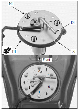
Clean around the fuel pump.
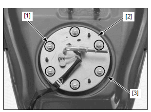
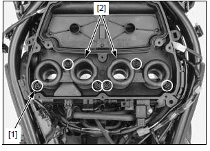
Loosen the six mounting nuts [1] in a crisscross pattern in several steps and remove them.
Be careful not to deform the float arm of the fuel level sensor.
Remove the fuel pump unit [2] and rubber seal [3].
Installation is in the reverse order of removal.
NOTE:
- Replace the rubber seal [1] with a new one.
- Clean the rubber seal seating areas of the fuel tank and fuel pump base plate, and be sure that no foreign materials are allowed.
- Place the rubber seal with the boss [2] facing toward the fuel pipe [3] and pull the three retaining pins [4] in the holes securely to seat it on the base plate.
- Tighten the six mounting nuts to the specified torque in the sequence as shown.
TORQUE:
Fuel pump mounting nut:
12 N*m (1.2 kgf*m, 9 lbf*ft)
DISASSEMBLY/INSPECTION
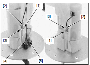
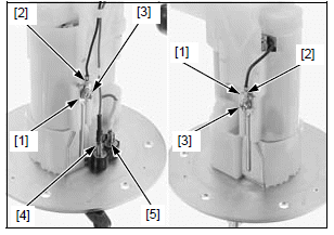
Remove the screws [1], Black wire terminals [2] and stoppers [3].
Disconnect the Pink wire connector [4] and Blue wire connector [5].
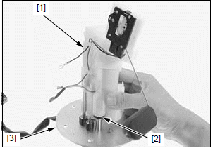
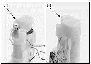
Remove the fuel pump unit assembly [1] and O-ring [2] from the fuel pump stay [3].
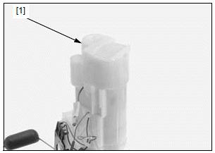
Remove the chamber [1].
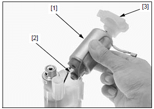
Remove the fuel pump [1] and O-ring [2].
Visually inspect the fuel pump filter [3] for dirt, debris or any clogging.
Replace fuel pump unit as an assembly if necessary.
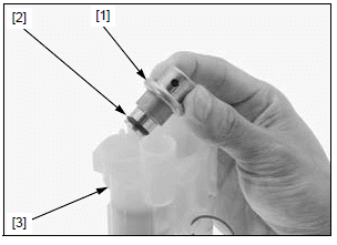
Remove the pressure regulator [1] and O-ring [2] from the fuel filter [3].
ASSEMBLY
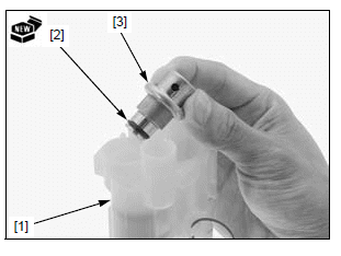
Replace the fuel filter [1] with a new one if necessary.
Install a new O-ring [2] to the pressure regulator [3].
Install the pressure regulator.
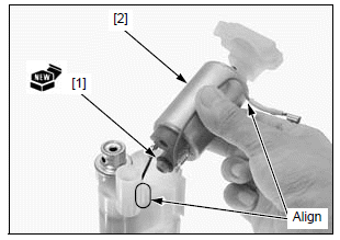
Install a new O-ring [1] to the fuel pump [2].
Install the fuel pump.
- Align the Blue wire with the fuel filter groove.
Insert the fuel pump filter edge [1] between the fuel pump and pressure regulator.
Install the chamber [2].
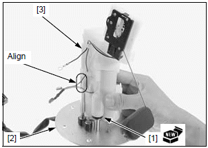
Install a new O-ring [1] to the fuel pump stay [2].
Install the fuel pump unit assembly [3] by aligning the grooves with the fuel pump stay tabs.
Install the stoppers [1], Black wire terminals [2] and screws [3].
Tighten the screws securely.
Connect the Pink wire connector [4] and Blue wire connector [5].
Air cleaner housing
REMOVAL/INSTALLATION
Remove the following:
- Fuel tank
- Air cleaner lid
Release the following:
- EOP switch 1P (White) connector [1] from the slot
- Clutch cable [2] from the wire guide [3]
- Wire clip [1]
- Wire clip [1]
- Front wheel speed sensor 2P (Blue) connector [2] from the stay
Disconnect the MAP sensor 3P (Black) connector [3] and vacuum hose [4] from the air cleaner housing.
Loosen the six screws [1] fully and remove the intake ducts [2].
Slightly pull up the air cleaner housing.
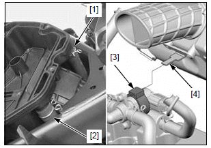
Disconnect the crankcase breather hose [1] and air supply hose [2] from the air cleaner housing.
Release the PAIR control valve [3] from the stay [4], then remove the air cleaner housing from the throttle body.
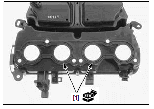
Remove the O-rings [1] from the air cleaner housing.
Installation is in the reverse order of removal.
- Replace the O-rings with new ones.
See also:
 Honda CBR650 - Service manual > Service information
GENERAL Bending or twisting the control cable will impair smooth operation and could cause the cables to stick or bind, resulting in loss of vehicle control. Work in a well ventilated area. Smoking or allowing flames or sparks in the work area or where gasoline is stored can cause a fire or explosion. Before disconnecting the fuel feed hose, relieve fuel pressure from the system. Do not snap the throttle valve from full open to full close after the throttle cable has been removed. It may cause incorrect idle operation. Seal the intake port with a piece of tape or a clean cloth to keep dirt and debris from entering the engine after the throttle body has been removed. Do not damage the throttle body. It may cause incorrect throttle valve operation. Prevent dirt and debris from entering the throttle bore and air passages after the throttle body has been removed. Clean them using a compressed air if necessary. Do not loosen or tighten the white painted nut and screw of the throttle body. Loosening or tightening them can cause throttle valve and idle control failure. Do not apply commercially available carburetor cleaners to the inside of the throttle bore. The parts of the throttle body not shown in this manual should not be disassembled. For fuel level sensor inspection. The following color codes are used throughout this section.
Honda CBR650 - Service manual > Throttle body
REMOVAL/INSTALLATION NOTE: Always clean around the fuel system parts with compressed air before removing to prevent dirt and debris from entering the air passages in the throttle body.
 Rider's Manual BMW R 1250 GS GSA
 Owner's Manual Harley-Davidson Sportster XL1200X Forty-Eight
 Owner's Manual Honda CBR650R
 Service manual Honda CBR650
 Owner's Manual Honda PCX125
 Owner's Manual Kawasaki Z1000SX
 Service manual Kawasaki Z1000SX
 Owner's Manual Lexmoto Echo
 Owner's Manual Royal Enfield Interceptor 650
 Service manual Royal Enfield Interceptor 650
 Owner's Manual Yamaha MT-07