 Honda CBR650 - Service manual > Hydraulic brake
Service information
GENERAL
CAUTION
Frequent inhalation of brake pad dust, regardless of material composition, could be hazardous to your health.
- Avoid breathing dust particles.
- Never use an air hose or brush to clean brake assemblies. Use an OSHA-approved vacuum cleaner.
NOTICE
Spilling brake fluid will severely damage instrument lenses and painted surface. It is also harmful to some rubber parts. Be careful whenever you remove the reservoir cover; make sure the front reservoir is horizontal first.
- This section covers service of the conventional brake components of the brake system. For Anti-lock Brake System (ABS; CBR650FA, CB650FA) service.
- The CBR650FA, CB650FA models are equipped with the ABS, however, the brake fluid replacement procedure is performed in the same manner as in the ordinary air bleeding procedure. Note that replacement and bleeding air from the brake fluid in the ABS modulator is not necessary, as it sealed in the modulator.
- A contaminated brake disc or pad reduces stopping power. Discard contaminated pads and clean a contaminated disc with a high quality brake degreasing agent.
- Always use fresh DOT 4 brake fluid from a sealed container when servicing the system. Do not mix different types of fluid, they may not be compatible.
- Never allow contaminates (dirt, water, etc.) to get into an open reservoir.
- Once the hydraulic system has been opened, or if the brake feels spongy, the system must be bled.
- Always check brake operation before riding the motorcycle.
- CBR650FA, CB650FA: When the wheel speed sensor is removed, be sure to check the air gap between the wheel speed sensor and pulser ring after installing it.
Troubleshooting
Brake lever/pedal soft or spongy
- Air in hydraulic system
- Leaking hydraulic system
- Contaminated brake pad/disc
- Worn caliper piston seal
- Worn master piston cups
- Worn brake pad/disc
- Contaminated caliper
- Contaminated master cylinder
- Caliper not sliding properly
- Low brake fluid level
- Clogged fluid passage
- Warped/deformed brake disc
- Sticking/worn caliper piston
- Sticking/worn master piston
- Bent brake lever/pedal
Brake lever/pedal hard
- Clogged/restricted fluid passage
- Sticking/worn caliper piston
- Caliper not sliding properly
- Worn caliper piston seal
- Sticking/worn master piston
- Bent brake lever/pedal
Brake drags
- Contaminated brake pad/disc
- Misaligned wheel
- Badly worn brake pad/disc
- Warped/deformed brake disc
- Caliper not sliding properly
- Clogged/restricted fluid passage
- Sticking caliper piston
Component location
FRONT:
CBR650FA shown:
REAR:
CBR650FA shown:
Brake fluid replacement/air bleeding
BRAKE FLUID DRAINING
For front brake:
Turn the handlebar so the reservoir is level.
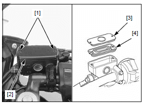
Remove the following:
- Two screws [1]
- Reservoir cap [2]
- Set plate [3]
- Diaphragm [4]
For rear brake:
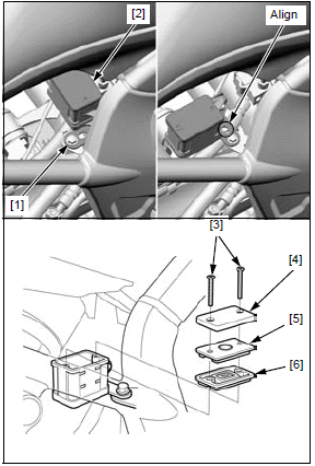
Loosen the stay bolt [1].
Slightly pull the reservoir [2] upward and turn it counterclockwise.
Align the groove with the tab, then temporarily tighten the reservoir stay bolt.
Take care not to spill the fluid out of the reservoir.
Remove the following:
- Two screws [3]
- Reservoir cap [4]
- Set plate [5]
- Diaphragm [6]
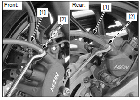
Connect a bleed hose [1] to the caliper bleed valve [2].
Loosen the bleed valve and pump the brake lever or pedal until no more fluid flows out of the bleed valve.
Close the bleed valve.
BRAKE FLUID FILLING/AIR BLEEDING
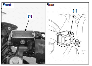
Fill the reservoir to the upper level line [1] with DOT 4 brake fluid from a sealed container.
Connect a commercially available brake bleeder to the bleed valve.
Operate the brake bleeder and loosen the bleed valve.
Check the fluid level often while bleeding to prevent air from being pumped into the system.
If an automatic refill system is not used, add fluid when the fluid level in the reservoir is low.
Perform the bleeding procedure until the system is completely flushed/bled.
Close the bleed valve and operate the brake lever or pedal. If it still feels spongy, bleed the system again.
If the brake bleeder is not available, use the following procedure.
Connect a bleed hose to the bleed valve.
Pump up the system pressure with the brake lever/ pedal until the lever/pedal resistance is felt.
Do not release the brake lever or pedal until the bleed valve has been closed.
1. Squeeze the brake lever or depress the brake pedal all the way, and loosen the bleed valve 1/4 of a turn.
Wait several seconds and then close it.
2. Release the brake lever/pedal slowly and wait several seconds after it reaches the end of its travel.
3. Repeat the steps 1 and 2 until there are no air bubbles in the bleed hose.
After bleeding the system completely, tighten the bleed valve to the specified torque.
TORQUE: 5.4 N*m (0.6 kgf*m, 4.0 lbf*ft)
Fill the reservoir to the upper level line with DOT 4 brake fluid.
For front brake:
Install the diaphragm, set plate, reservoir cap and tighten the screws to the specified torque.
TORQUE: 1.5 N*m (0.2 kgf*m, 1.1 lbf*ft)
For rear brake:
Install the diaphragm, set plate, reservoir cap and tighten the screws to the specified torque.
TORQUE: 1.5 N*m (0.2 kgf*m, 1.1 lbf*ft)
Loosen the reservoir stay bolt [1] and set the reservoir [2] in position.
Attach the stopper of the reservoir stay [3] against the groove surface, then tighten the reservoir stay bolt securely.
Brake pad/disc
BRAKE PAD REMOVAL/ INSTALLATION
Check the fluid level in the reservoir as this operation causes the fluid level to rise.
NOTE:
- If you replace the brake pads with new ones, push the caliper pistons
all the way in by pushing the caliper body inward to allow installation of
new brake pads before removing the pads.
Always replace the brake pads in pairs to ensure even disc pressure.
FRONT
Do not operate the brake lever after removing the pads.
Remove the pad pin [1] by pushing the pads against the pad spring, then the brake pads [2] out of the caliper.
Make sure the pad spring [1] is installed in position.
Be sure the stopper ring [2] on the pad pin is in good condition, and replace it with a new one if necessary.
Coat the stopper ring with silicone grease.
Install the pads [3] so that their ends are set in the retainer [4] properly.
Install the pad pin [5] by pushing the pads against the pad spring to align the pad pin holes in the pads and caliper body.
Tighten the pad pin to the specified torque.
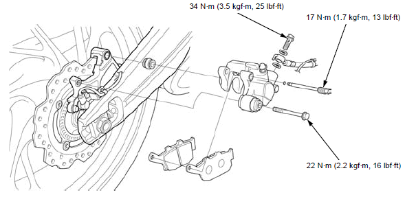
TORQUE: 17 N*m (1.7 kgf*m, 13 lbf*ft)
Operate the brake lever to seat the caliper pistons against the pads.
REAR
Loosen the pad pin [1] and remove the caliper bolt [2].
Do not operate the brake pedal after removing the pads.
Pivot the caliper body up, and remove the pad pin and brake pads [3].
Make sure the pad spring [1] is installed in position.
Be sure the stopper ring [2] on the pad pin is in good condition, and replace it with a new one if necessary.
Coat the stopper ring with silicone grease.
Install the pads [3] so that their ends are rest on the pad retainer [4] properly.
Lower the caliper body and loosely install a new caliper bolt [5].
Install the pad pin [6] by pushing the pads against the pad spring to align the pad pin holes in the pads and caliper body.
Tighten the caliper bolt to the specified torque.
TORQUE: 22 N*m (2.2 kgf*m, 16 lbf*ft)
Tighten the pad pin to the specified torque.
TORQUE: 17 N*m (1.7 kgf*m, 13 lbf*ft)
Operate the brake pedal to seat the caliper piston against the pads.
BRAKE DISC INSPECTION
Visually inspect the brake disc for damage or cracks.
Measure the brake disc according to HYDRAULIC BRAKE SPECIFICATIONS and replace if necessary.
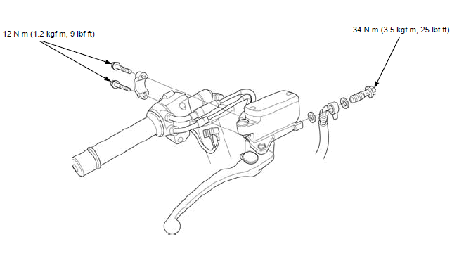
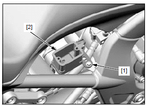
Front master cylinder
REMOVAL/INSTALLATION
Drain the brake fluid from the front brake hydraulic system.
When removing the oil bolt, cover the end of the brake hose to prevent contamination.
Remove the following:
- Brake light switch connectors [1]
- Oil bolt [2]
- Sealing washers [3]
- Brake hose [4]
- Two bolts [1]
- Master cylinder holder [2]
- Master cylinder [3]
Installation is in the reverse order of removal.
NOTE:
- Replace the sealing washers with new ones.
- Install the master cylinder holder with the "UP" mark [4] facing up.
- Align the edge of the master cylinder with the punch mark on the handlebar, and tighten the upper bolt first then tighten the lower bolt.
- Be sure to set the eyelet joint onto the stopper [5] when connecting the brake hose.
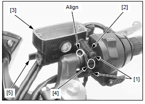
TORQUE:
Front master cylinder holder bolt: 12 N*m (1.2 kgf*m, 9 lbf*ft)
Oil bolt: 34 N*m (3.5 kgf*m, 25 lbf*ft)
Fill and bleed the front brake hydraulic system.
DISASSEMBLY/ASSEMBLY
Disassemble and assemble the front master cylinder as following illustration.
- Do not allow the piston cup lips to turn inside out.
- Install the snap ring with the chamfered edge facing the thrust load side and be certain it is firmly seated in the groove. Do not reuse the snap ring which could easily spin in the groove.
- Align the switch boss with the master cylinder hole properly.
- When tightening the pivot nut, hold the pivot bolt securely.
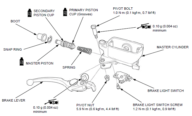
INSPECTION
Check the following parts for scoring, scratches, deterioration or damage.
- Master cylinder
- Master piston
- Piston cups
- Spring
- Boot
Measure the parts according to HYDRAULIC BRAKE SPECIFICATIONS and replace if necessary.
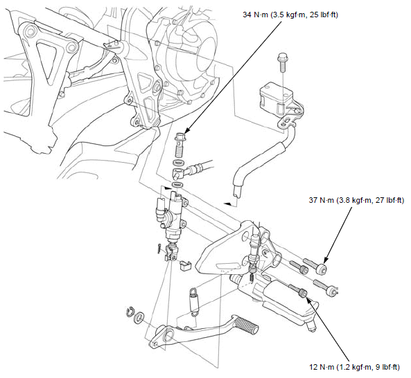
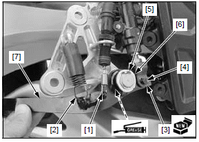
Rear master cylinder
REMOVAL/INSTALLATION
Drain the brake fluid from the rear brake hydraulic system.
Remove the stay bolt [1] and rear brake reservoir [2].
When removing the oil bolt, cover the end of the brake hose to prevent contamination.
Disconnect the brake hose [1] by removing the oil bolt [2] and sealing washers [3].
Loosen the master cylinder mounting bolts [4].
Support the right rider footpeg bracket [5] securely and remove the bracket bolts [6].
Remove the following.
- Cotter pin [1]
- Joint pin [2]
- Mounting bolts [3]
- Master cylinder [4]
Installation is in the reverse order of removal.
NOTE:
- Replace the sealing washers and cotter pin with new ones.
- Be sure to rest the eyelet stopper pin against the stopper when tightening the oil bolt.
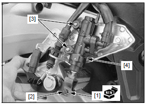
TORQUE:
Rider footpeg bracket bolt:
37 N*m (3.8 kgf*m, 27 lbf*ft)
Rear master cylinder mounting bolt:
12 N*m (1.2 kgf*m, 9 lbf*ft)
Oil bolt:
34 N*m (3.5 kgf*m, 25 lbf*ft)
Fill and bleed the rear brake hydraulic system.
DISASSEMBLY/ASSEMBLY
Disassemble and assemble the rear master cylinder as following illustration.
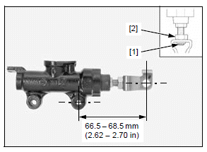
- Adjust the push rod length between the center of the lower mounting bolt hole and center of the joint pin hole when installing the push rod joint.
- Do not allow the piston cup lips to turn inside out.
- Install the snap ring with the chamfered edge facing the thrust load side and be certain it is firmly seated in the groove. Do not reuse the snap ring which could easily spin in the groove.
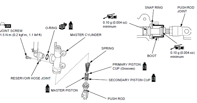
When the push rod has been disassembled, adjust the push rod length so that the distance from the center of the master cylinder lower mounting bolt hole to the center of the joint pin hole is standard length as shown.
If the length is adjusted to the longer position, make sure that the lower end of the push rod thread [1] is visible inside the joint.
After adjustment, tighten the joint nut [2] to the specified torque.
TORQUE:
Rear master cylinder push rod joint nut:
17 N*m (1.7 kgf*m, 13 lbf*ft)
INSPECTION
Check the following parts for scoring, scratches, deterioration or damage.
- Master cylinder
- Master piston
- Piston cups
- Spring
- Boot
Measure the parts according to HYDRAULIC BRAKE SPECIFICATIONS and replace if necessary.
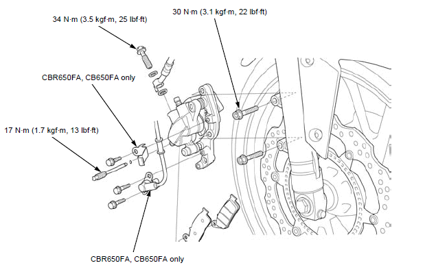
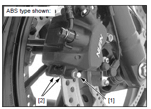
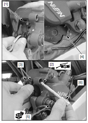
Front brake caliper
REMOVAL/INSTALLATION
Drain the brake fluid from the front brake hydraulic system.
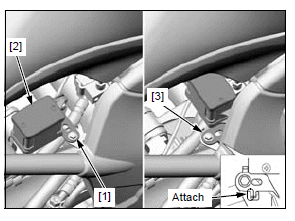
CBR650FA/ CB650FA:
Remove the following:
- Bolt [1] and wire clamp [2]
- Two bolts [3] and front wheel speed sensor [4]
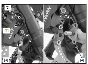
When removing the oil bolt, cover the end of brake hose to prevent contamination.
- Brake pads [1]
- Oil bolt [2]
- Sealing washers [3]
- Brake hose [4]
- Mounting bolts [5]
- Brake caliper [6]
Installation is in the reverse order of removal.
NOTE:
- Replace the brake caliper mounting bolts and sealing washers with new ones.
- Be sure to rest the eyelet stopper pin against the caliper body when tightening the oil bolt.
- CBR650FA/CB650FA: Before installing the wheel speed sensor, wipe the sensor tip and mounting area to remove any foreign material.
TORQUE:
Front brake caliper mounting bolt:
30 N*m (3.1 kgf*m, 22 lbf*ft)
Oil bolt:
34 N*m (3.5 kgf*m, 25 lbf*ft)
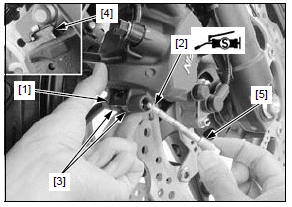
DISASSEMBLY/ASSEMBLY
Disassemble and assemble the front brake caliper as following illustration.
For brake pad removal/installation.
- Mark the pistons to ensure that they are reinstalled in their original locations.
- When removing the caliper pistons with compressed air, place a shop towel over the pistons to prevent damaging the pistons and caliper body. Do not use high pressure or bring the nozzle too close to the fluid inlet.
- Install the pistons with the opening toward the pads.
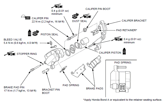
INSPECTION
Check the following parts for scoring, scratches, deterioration or damage.
- Caliper cylinders
- Caliper pistons
Measure the parts according to HYDRAULIC BRAKE SPECIFICATIONS and replace if necessary.
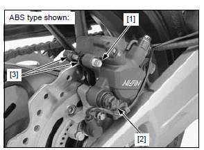
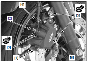
Rear brake caliper
REMOVAL/INSTALLATION
Drain the brake fluid from the rear brake hydraulic system.
When removing the oil bolt, cover the end of brake hose to prevent contamination.
- Oil bolt [1]
- Sealing washers [2]
- Brake hose [3]
- Brake pads
- Brake caliper [4]
- Caliper pin boot [5]
Installation is in the reverse order of removal.
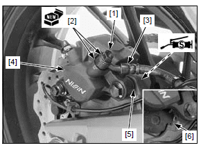
NOTE:
- Replace the sealing washers with new ones.
- If the pad retainer [6] was removed, apply Honda Bond A or equivalent to the retainer seating surface.
- Apply 0.4 g (0.01oz) minimum of silicone grease to the sliding area of the caliper pin bolt.
- Be sure to rest the eyelet stopper pin against the caliper body when tightening the oil bolt.
TORQUE: Oil bolt: 34 N*m (3.5 kgf*m, 25 lbf*ft)
Fill and bleed the rear brake hydraulic system.
DISASSEMBLY/ASSEMBLY
Disassemble and assemble the rear brake caliper as following illustration.
- When removing the caliper piston with compressed air, place a shop towel over the piston to prevent damaging the piston and caliper body. Do not use high pressure or bring the nozzle too close to the fluid inlet.
- Install the piston with the opening toward the pads.
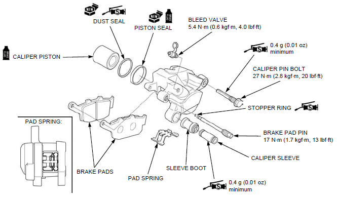
INSPECTION
Check the following parts for scoring, scratches, deterioration or damage.
- Caliper cylinder
- Caliper piston
Measure the parts according to HYDRAULIC BRAKE SPECIFICATIONS and replace if necessary.
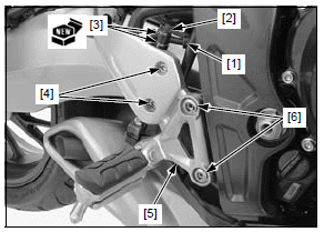
Brake pedal
REMOVAL/INSTALLATION
Support the right rider footpeg bracket [1] securely and remove the bracket bolts [2].
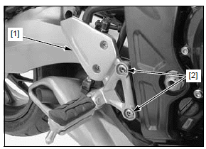
Remove the following:
- Switch spring [1]
- Return spring [2]
- Cotter pin [3]
- Joint pin [4]
- Snap ring [5]
- Washer [6]
- Brake pedal [7]
Installation is in the reverse order of removal.
NOTE:
- Apply grease to the pedal pivot sliding area (grease groove).
- Install the snap ring with the chamfered edge facing the thrust load side and be certain it is firmly seated in the groove. Do not reuse the snap ring which could easily spin in the groove.
- Replace the cotter pin with a new one.
- Install each spring in the direction as shown.
TORQUE:
Rider footpeg bracket bolt: 37 N*m (3.8 kgf*m, 27 lbf*ft)
See also:
 Honda CBR650 - Service manual > Rear wheel/suspension
Service information GENERAL A hoist or equivalent is required to support the motorcycle when servicing the rear wheel and suspension. A contaminated brake disc or pad reduces stopping power. Discard contaminated pads and clean a contaminated disc with a high quality brake degreasing agent. Do not operate the brake pedal after removing the rear wheel. Use only tires marked "TUBELESS" and tubeless valves on rim marked "FOR TUBELESS". After the rear wheel installation, check the brake operation by applying the brake pedal. CBR650FA, CB650FA: After the rear wheel installation, perform the air gap inspection. Use only genuine Honda replacement bolts and nuts for all suspension pivots and mounting points. For brake system service.
 Rider's Manual BMW R 1250 GS GSA
 Owner's Manual Harley-Davidson Sportster XL1200X Forty-Eight
 Owner's Manual Honda CBR650R
 Service manual Honda CBR650
 Owner's Manual Honda PCX125
 Owner's Manual Kawasaki Z1000SX
 Service manual Kawasaki Z1000SX
 Owner's Manual Lexmoto Echo
 Owner's Manual Royal Enfield Interceptor 650
 Service manual Royal Enfield Interceptor 650
 Owner's Manual Yamaha MT-07