 Honda CBR650 - Service manual > Rear wheel/suspension
Service information
GENERAL
- A hoist or equivalent is required to support the motorcycle when servicing the rear wheel and suspension.
- A contaminated brake disc or pad reduces stopping power. Discard contaminated pads and clean a contaminated disc with a high quality brake degreasing agent.
- Do not operate the brake pedal after removing the rear wheel.
- Use only tires marked "TUBELESS" and tubeless valves on rim marked "FOR TUBELESS".
- After the rear wheel installation, check the brake operation by applying the brake pedal.
- CBR650FA, CB650FA: After the rear wheel installation, perform the air gap inspection.
- Use only genuine Honda replacement bolts and nuts for all suspension pivots and mounting points.
- For brake system service.
Troubleshooting
Steers to one side or does not track straight
- Drive chain adjusters not adjusted equally
- Bent axle
- Damaged frame
- Worn swingarm pivot components
Rear wheel wobbles
- Bent rim
- Faulty tire
- Worn or damaged wheel bearings
- Worn or damaged driven flange bearing
- Axle not tightened properly
- Faulty swingarm pivot bearings
- Suspension fasteners not tightened properly
- Unbalanced tire and wheel
Wheel hard to turn
- Faulty wheel bearings
- Bent axle
- Faulty driven flange bearing
- Drive chain too tight
- Brake drag
Soft suspension
- Low tire pressure
- Incorrect suspension adjustment
- Weak shock absorber spring
- Oil leakage from damper unit
Stiff suspension
- High tire pressure
- Incorrect suspension adjustment
- Bent shock absorber damper rod
- Damaged suspension or swingarm pivot bearings
- Improperly tightened swingarm pivot
Rear suspension noise
- Loose suspension fasteners
- Worn or damaged suspension pivot bearings
- Faulty shock absorber
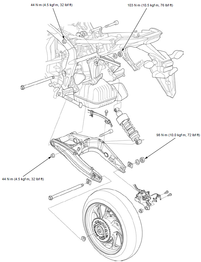
Component location
CBR650FA shown:
Rear wheel
REMOVAL/INSTALLATION
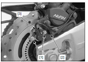
CBR650FA, CB650FA:
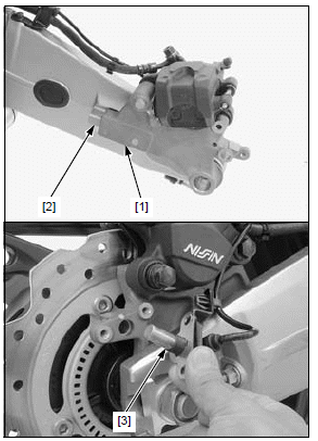
Remove the following:
- Two bolts [1]
- Wire stay [2]
- Rear wheel speed sensor [3]
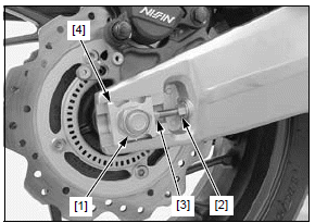
Loosen the axle nut [1].
Support the motorcycle using a hoist or equivalent and raise the rear wheel off the ground.
Loosen the lock nuts [2] and turn the adjusting bolts [3] so the wheel can be moved forward all the way.
Support the caliper so it does not hang from the brake hose. Do not twist the brake hose
Remove the axle nut and right adjusting plate [4]
Push the rear wheel forward.
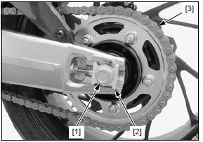
Remove the axle [1] and left adjusting plate [2].
Derail the drive chain [3] from the driven sprocket and remove the rear wheel.
NOTE:
- Do not operate the brake pedal after removing the wheel.
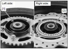
Remove the following:
- Left side collar (flange) [1]
- Right side collar [2]
Installation is in the reverse order of removal.
NOTE:
- When installing the wheel, take care not to let the caliper bracket [1] come off the swingarm boss [2] and not to damage the brake pads.
- The axle is installed from the left side.
- CBR650FA/CB650FA: Before installing the rear wheel speed sensor [3], wipe the sensor tip and mounting area to remove any foreign material.
Adjust the drive chain slack.
TORQUE:
Rear axle nut: 98 N*m (10.0 kgf*m, 72 lbf*ft)
CBR650FA/ CB650FA:
Check the air gap between the wheel speed sensor and pulser ring.
INSPECTION
Turn the inner race of each bearing with your finger.
The bearings should turn smoothly and quietly. Also check that the bearing outer race fits tightly in the hub.
Replace the bearings if they do not turn smoothly, quietly, or if they fit loosely in the hub.
Inspect the following parts for damage, abnormal wear, deformation or bend.
- Rear axle
- Wheel hub
- Wheel rim
- Driven sprocket
- Damper rubbers
Measure each part according to REAR WHEEL/ SUSPENSION SPECIFICATIONS.
Replace any part if it is out of service limit.
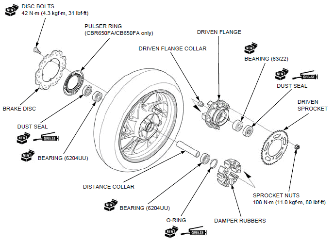
DISASSEMBLY/ASSEMBLY
Disassemble and assemble the rear wheel as following illustration.
- For wheel balance service.
- Install the rear wheel dust seal with the flat side facing out so that it is flush with the wheel hub.
- Install driven flange dust seal with the flat side facing out so that it is flush with the driven flange end face.
- Install the brake disc with the rotation mark (arrow) facing out.
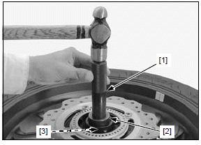
BEARING REPLACEMENT
WHEEL BEARING
Install the bearing remover head [1] into the bearing.
From the opposite side of the wheel, install the bearing remover shaft [2] and drive the bearing out of the wheel hub.
TOOLS:
Bearing remover head, 20 mm 07746-0050600
Bearing remover shaft 07746-0050100
Remove the distance collar and drive out the other bearing.
Drive in a new right side bearing (brake disc side) squarely with the marked side facing up until it is fully seated.
Install the distance collar.
Drive in a new left side bearing squarely with the marked side facing up until it is fully seated.
TOOLS:
[1] Driver 07749-0010000
[2] Attachment, 42 x 47 mm 07746-0010300
[3] Pilot, 20 mm 07746-0040500
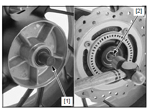
DRIVEN FLANGE BEARING
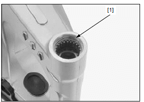
Drive out the driven flange collar [1] and the bearing [2].
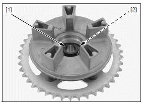
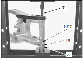
Place a new bearing [1] with the marked side facing down. Install the driven flange collar [2] into the bearing until it is fully seated.
TOOLS:
[3] Driver 07749-0010000
[4] Attachment, 28 x 30 mm 07946-1870100
[5] Pilot, 20 mm 07746-0040500
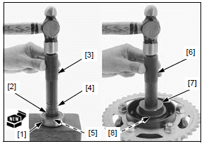
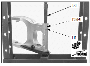
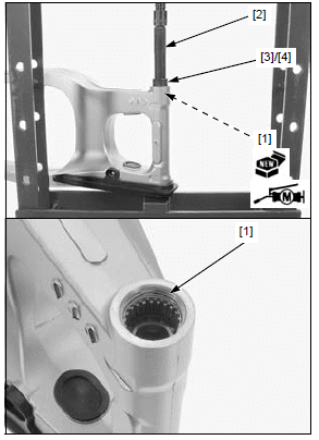
Drive in the driven flange bearing/collar squarely with the collar side facing down until it is fully seated.
TOOLS:
[6] Driver 07749-0010000
[7] Attachment, 52 x 55 mm 07746-0010400
[8] Pilot, 20 mm 07746-0040500
Shock absorber
REMOVAL/INSTALLATION
Remove the drive chain cover/mud guard.
Lift the fuel tank and support it.
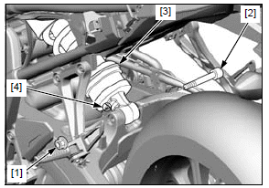
Remove the shock absorber upper mounting nut [1] and bolt [2].
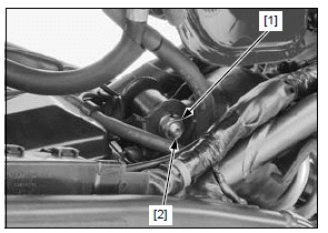
Remove the shock absorber lower mounting nut [1] and bolt [2].
Remove the shock absorber [3] out of the frame.
Installation is in the reverse order of removal.
NOTE:
- Turn the drain hole [4] to the lower side.
- The mounting bolt is installed from the right side.
TORQUE:
Shock absorber mounting nut:
44 N*m (4.5 kgf*m, 32 lbf*ft)
DISASSEMBLY/ASSEMBLY
Remove the pivot collar [1] and dust seals [2].
Apply molybdenum disulfide grease to rotating areas of the needle bearings.
Apply molybdenum disulfide grease to the lips of new dust seals.
Install each dust seal with the flat side facing out so that it is flush with the end surface.
Install the pivot collar.
INSPECTION
Inspect the following parts of the shock absorber for damage, abnormal wear, oil leakage or bend.
- Damper unit
- Pivot bushing
- Needle bearing
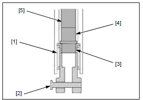
BEARING REPLACEMENT
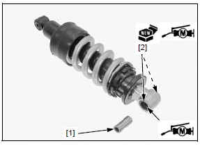
Press the needle bearing out of the shock absorber using the special tools.
TOOLS:
[1] Driver 07949-3710001
[2] Attachment, 22 x 24 mm 07746-0010800
[3] Pilot, 17 mm 07746-0040400
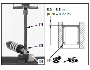
Apply molybdenum disulfide grease to rotating areas of a new needle bearing.
Carefully press in the bearing [4] with the marked side facing up until the depth from the pivot end surface is 5.0 - 5.5 mm (0.20 - 0.22 in), using the same tools.
SHOCK ABSORBER DISPOSAL PROCEDURE
Center punch the shock absorber to mark the drilling point.
Wrap the shock absorber inside a plastic bag.
Support the shock absorber in a vise as shown.
Through the open end of the bag, insert a drill motor with a sharp 2 - 3 mm (5/64 - 1/8 in) drill bit.
NOTICE
- Do not use a dull drill bit which could cause a build-up of excessive heat and pressure inside the damper, leading to an explosion and severe injury.
- The shock absorber contains nitrogen gas and oil under high pressure. Do not drill any further down the damper case than the measurement given above, or you may drill into the oil chamber. Then high pressure oil may cause serious injury.
- Always wear eye protection to avoid getting metal shavings in your eyes when the gas pressure is released. The plastic bag is only intended to shield you from the escaping gas.
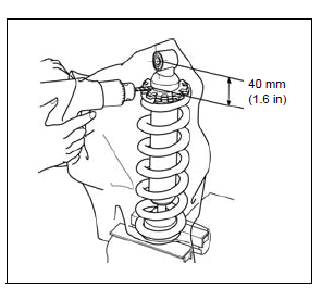
Hold the bag around the drill motor and briefly run the drill motor inside the bag; this will inflate the bag with air from the motor and help keep the bag from getting caught in the bit when you start.
Swingarm
REMOVAL/INSTALLATION
Remove the following:
- Drive chain cover/mud guard
- Rear wheel
- EVAP canister (TH model only)
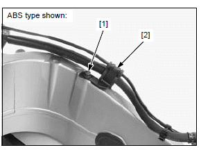
Remove the bolt [1] and hose clamp [2].
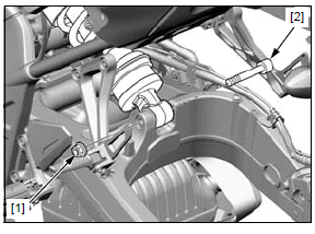
Remove the shock absorber lower mounting nut [1] and bolt [2].
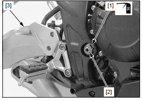
Remove the pivot nut [1] and the bolt [2].
Support the caliper so it does not hang from the brake hose. Do not twist the brake hose
Move the brake hose, speed sensor wire and drive chain out of the way and remove the swingarm [3] from the frame.
Installation is in the reverse order of removal.
NOTE:
- The pivot bolt is installed from the left side.
- Apply engine oil to the threads and seating surface of the pivot nut.
TORQUE:
Swingarm pivot nut:
103 N*m (10.5 kgf*m, 76 lbf*ft)
Shock absorber mounting nut:
44 N*m (4.5 kgf*m, 32 lbf*ft)
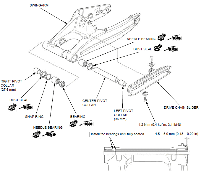
DISASSEMBLY/ASSEMBLY
Disassemble and assemble the swingarm as following illustration.
- Install each dust seal with the flat side facing out so that it is flush with the pivot end surface.
INSPECTION
Inspect the following parts for damage, abnormal wear, deformation.
- Swingarm
- Pivot collars
- Bearings
- Drive chain slide
SWINGARM PIVOT BEARING REPLACEMENT
RIGHT SIDE
Remove the snap ring [1].
Press the ball bearing [1] and needle bearing [2] out of the right pivot using the special tools.
TOOLS:
[3] Driver, 15 x 280L 07949-3710001
[4] Attachment, 24 x 26 mm 07746-0010700
[5] Pilot 20 mm 07746-0040500
Apply molybdenum disulfide grease to the rotating area of a new ball bearing [1].
Install the ball bearing into the right pivot with the marked side facing out until it is fully seated using a hydraulic press and special tools as shown.
TOOLS:
[2] Driver 07749-0010000
[3] Attachment, 37 mm 07ZMD-MBW0200
[4] Pilot 20 mm 07746-0040500
Apply molybdenum disulfide grease to a new needle bearing rotating area.
Install the needle bearing [1] into the right pivot with the marked side facing out until it is fully seated using a hydraulic press and special tools as shown.
TOOLS:
[2] Driver 07749-0010000
[3] Attachment, 37 mm 07ZMD-MBW0200
[4] Pilot 30 mm 07746-0040700
Install the snap ring [1] into the right pivot groove securely.
NOTE:
- Do not reuse the snap ring which could easily spin in the groove.
- Make sure that the snap ring is firmly seated in the groove.
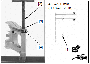
LEFT SIDE
Press the needle bearing [1] out of the swingarm using the special tools.
TOOLS:
[2] Remover attachment, 28 mm 07HMC-MR70100
[3] Pilot 17 mm 07746-0040400
[4] Attachment, 22 x 24 mm 07746-0010800
[5] Driver, 15 x 280L 07949-3710001
Apply molybdenum disulfide grease to the rotating area of a new needle bearing [1].
Carefully press the bearing in the left pivot with the marked side facing up until the depth from the pivot end surface is 4.5 - 5.0 mm (0.18 - 0.20 in), using the special tools.
TOOLS:
[2] Driver 07749-0010000
[3] Attachment, 37 mm 07ZMD-MBW0200
[4] Pilot, 28 mm 07746-0041100 or 07JAD-PH80400
See also:
 Honda CBR650 - Service manual > Steering stem
REMOVAL CBR650F/FA: Remove the following: Middle cowls Horn Disconnect the ignition switch 2P (Brown) connector [1] and immobilizer receiver 4P (Black) connector [2].
Honda CBR650 - Service manual > Hydraulic brake
Service information GENERAL CAUTION Frequent inhalation of brake pad dust, regardless of material composition, could be hazardous to your health. Avoid breathing dust particles. Never use an air hose or brush to clean brake assemblies. Use an OSHA-approved vacuum cleaner.
 Rider's Manual BMW R 1250 GS GSA
 Owner's Manual Harley-Davidson Sportster XL1200X Forty-Eight
 Owner's Manual Honda CBR650R
 Service manual Honda CBR650
 Owner's Manual Honda PCX125
 Owner's Manual Kawasaki Z1000SX
 Service manual Kawasaki Z1000SX
 Owner's Manual Lexmoto Echo
 Owner's Manual Royal Enfield Interceptor 650
 Service manual Royal Enfield Interceptor 650
 Owner's Manual Yamaha MT-07