 Honda CBR650 - Service manual > Immobilizer system (HISS)
Service information
GENERAL
- When checking the immobilizer system (HISS), follow the steps in the troubleshooting flow chart.
- Keep the immobilizer key away from the other vehicle's immobilizer key when using it. The jamming of the key code signal may occur and the proper operation of the system will be obstructed.
- The key has built-in electronic part (transponder). Do not drop and strike the key against a hard material object, and do not leave the key on the dashboard in the car, etc. where the temperature will rise. Do not leave the key in the water for a prolonged time such as by washing the clothes.
- The ECM as well as the transponder keys must be replaced if all transponder keys have been lost.
- The system does not function with a duplicated key unless the code is registered into the transponder with the immobilizer system (HISS).
- The ECM can store up to four key codes (The four keys can be registered).
- Do not modify the immobilizer system as it can cause the system failure (The engine cannot be started).
- For ignition system inspection.
- For ignition switch inspection.
- For engine stop switch inspection.
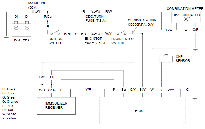
- The following color codes are used throughout this section.
Bl = Black
Br = Brown
Bu = Blue
G = Green
Gr = Gray
Lb = Light Blue
Lg = Light Green
O = Orange
P = Pink
R = Red
V = Violet
W = White
Y = Yellow
System location
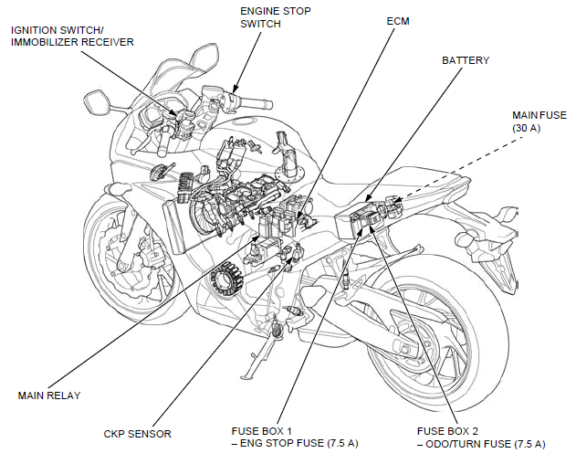
- IGNITION SWITCH/ IMMOBILIZER RECEIVER
- ENGINE STOP SWITCH
- ECM
- BATTERY
- MAIN FUSE (30 A)
- FUSE BOX 2
- ODO/TURN FUSE (7.5 A) - FUSE BOX 1
- ENG STOP FUSE (7.5 A) - CKP SENSOR
- MAIN RELAY
System diagram
Key registration procedures
When the key has been lost, or additional spare key is required:
1. Obtain a new transponder key.
2. Grind the key in accordance with the shape of the original key.
3. Apply 12 V battery voltage to the CKP sensor lines of the ECM using the special tool.
4. Turn the engine stop switch " "
and the ignition switch ON with the original key. The HISS indicator comes on
and it remains on.
"
and the ignition switch ON with the original key. The HISS indicator comes on
and it remains on.
- The code of the original key recognized by the ECM.
- If there is any problem in the immobilizer system (HISS), the system will enter the diagnostic mode and the indicator will remain on for approx. ten seconds, then it will indicate the diagnostic code.
5. Disconnect the red clip of the inspection adaptor from the battery positive (+) terminal for two seconds or more, then connect it again. The indicator remains on for approx. two seconds, then it blinks four times repeatedly.
- The immobilizer system (HISS) enters the registration mode.
Registrations of all key except the original key inserted in the ignition
switch are cancelled (Registration of the lost key or spare key is
cancelled).
The spare key must be registered again.
6. Turn the ignition switch OFF and remove the key.
7. Turn the ignition switch ON with a new key or the spare key (Never use the key registered in previous steps). The indicator comes on for two seconds then it blinks four times repeatedly.
- The new key or spare key is registered in the ECM.
- If there is any problem in the registration, the system will enter the diagnostic mode and the indicator will remain for approx. ten seconds, then it will indicate the diagnostic code.
- Keep the other transponder key away from the immobilizer receiver more than 50 mm (2.0 in).
8. Repeat the steps 6 and 7 when you continuously register the other new key.
The ECM can store up to four key codes (The four keys can be registered).
9. Turn the ignition switch OFF, remove the inspection adaptor and connect the CKP sensor 2P (Black) connector.
10.Turn the ignition switch ON with the registered key.
- The immobilizer system (HISS) returns to the normal mode.
11.Check that the engine can be started using all registered keys.
When the ignition switch is faulty:
1. Obtain a new ignition switch assembly.
2. Remove the ignition switch.
3. Apply 12 V battery voltage to the CKP sensor lines of the ECM using the special tool.
4. Set the original (registered) key near the immobilizer receiver so that the transponder in the key can communicate with the receiver.
5. Turn the engine stop switch "".
Connect a new ignition switch to the wire harness and turn it to ON with a new
transponder key (keep the ignition switch away from the receiver). The HISS
indicator comes on and it remains on.
- The code of the original key recognized by the ECM.
- If there is any problem in the immobilizer system (HISS), the system will enter the diagnostic mode and the indicator will remain on for approx. ten seconds, then it will indicate the diagnostic code.
6. Disconnect the red clip of the inspection adaptor from the battery positive (+) terminal for two seconds or more, then connect it again. The indicator remains on for approx. two seconds then it blinks four times repeatedly.
- The immobilizer system (HISS) enters the registration mode. Registrations of all key except the original key set near the receiver are cancelled.
7. Turn the ignition switch OFF and remove the key.
8. Install the ignition switch.
9. Turn the ignition switch ON with a first new key. The indicator comes on for two seconds then it blinks four times repeatedly.
- The first key is registered in the ECM.
- If there is any problem in the registration, the system will enter the diagnostic mode and the indicator will remain for approx. ten seconds, then it will indicate the diagnostic code.
10.Turn the ignition switch OFF and disconnect the red clip of the inspection adaptor from the battery positive (+) terminal.
11.Turn the ignition switch ON (with the first key registered in step 9). The HISS indicator comes on for two seconds then it goes off.
- The immobilizer system (HISS) returns to the normal mode.
12.Turn the ignition switch OFF and connect the red clip of the inspection adaptor to the battery positive (+) terminal.
13.Turn the ignition switch ON (with the first key registered in step 9). The HISS indicator comes on and it remains on.
- The code if the first key is recognized by the ECM.
- If there is any problem in the immobilizer system (HISS), the system will enter the diagnostic mode and the indicator will remain on for approx. ten seconds, then it will indicate the diagnostic code.
14.Disconnect the red clip of the inspection adaptor from the battery positive (+) terminal for two seconds or more, then connect it again. The indicator remains on for approx. two seconds then it blinks four times repeatedly.
- The immobilizer system (HISS) enters the registration mode. Registration of the original key used in step 4 is cancelled.
15.Turn the ignition switch OFF and remove the key.
16.Turn the ignition switch ON with a second new key (Never use the key registered in previous step). The indicator comes on for two seconds then it blinks four times repeatedly.
- The second key is registered in the ECM.
- If there is any problem in the registration, the system will enter the diagnostic mode and the indicator will remain for approx. ten seconds, then it will indicate the diagnostic code.
- Keep the other transponder key away from the immobilizer receiver more than 50 mm (2.0 in).
17.Repeat the steps 15 and 16 when you continuously register the other new key.
The ECM can store up to four key codes (The four keys can be registered).
18.Turn the ignition switch OFF, remove the inspection adaptor and connect the CKP sensor 2P (Black) connector.
19.Turn the ignition switch ON with the registered key.
- The immobilizer system (HISS) returns to the normal mode.
20.Check that the engine can be started using all registered keys.
When all keys have been lost:
1. Obtain a new ECM and new key set.
2. Replace the ignition switch with a new one.
3. Replace the ECM with a new one.
4. Turn the engine stop switch ""
and the ignition switch ON with a first new key. The HISS indicator comes on for
two seconds, then it blinks four times repeatedly.
- The first key is registered in the ECM.
- If there is any problem in the registration, the system will enter the diagnostic mode and the indicator will remain for approx. ten seconds, then it will indicate the diagnostic code.
5. Turn the ignition switch OFF and remove the first key.
6. Turn the ignition switch ON with a second new key. The HISS indicator comes on for two seconds, then it blinks four times repeatedly.
- The second key is registered in the ECM.
- If there is any problem in the registration, the system will enter the diagnostic mode and the indicator will remain for approx. ten seconds, then it will indicate the diagnostic code.
7. Turn the ignition switch OFF and remove the second key.
- The system will not enter the normal mode unless the two keys are registered in ECM.
- The third new key cannot be continuously registered. When it is necessary to register the third key, follow the procedures "When the key has been lost, or additional key is required".
8. Check that the engine can be started using all registered keys.
9. Replace the remaining key set parts.
When the ECM is faulty:
1. Obtain a new ECM and two new transponder keys.
2. Grind the keys in accordance with the shape of the original key.
3. Replace the ECM with a new one.
4. Turn the engine stop switch ""
and the ignition switch ON with a first new key. The HISS indicator comes on for
two seconds, then it blinks four times repeatedly.
- The first key is registered in the ECM.
- If there is any problem in the registration, the system will enter the diagnostic mode and the indicator will remain for approx. ten seconds, then it will indicate the diagnostic code.
5. Turn the ignition switch OFF and remove the first key.
6. Turn the ignition switch ON with a second new key. The HISS indicator comes on for two seconds, then it blinks four times repeatedly.
- The second key is registered in the ECM.
- If there is any problem in the registration, the system will enter the diagnostic mode and the indicator will remain for approx. ten seconds, then it will indicate the diagnostic code.
7. Turn the ignition switch OFF and remove the second key.
- The system will not enter the normal mode unless the two keys are registered in ECM.
- The third new key cannot be continuously registered. When it is necessary to register the third key, follow the procedures "When the key has been lost, or additional key is required".
8. Check that the engine can be started using all registered keys.
Diagnostic code indication
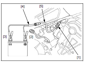
Turn the ignition switch OFF.
Disconnect the CKP sensor 2P (Black) connector [1].
Connect the adaptors to the wire harness side connector.
Connect the Red clip [2] of the adaptor to the 12 V battery positive (+) terminal and Black clip [3] to the negative (-) terminal.
TOOLS:
[4] Inspection adaptor 07XMZ-MBW0101
[5] Test harness adaptor 070MZ-MGE0100
Turn the engine stop switch ""
and the ignition switch ON with the properly registered key.
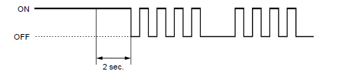
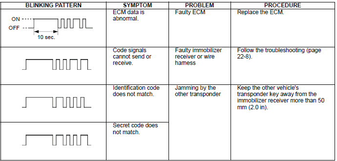
The HISS indicator will come on for approx. ten seconds then it will start blinking to indicate the diagnostic code if the system is abnormal.
The blinking frequency is repeated.
The HISS indicator remains on when the system is normal (The system is in the normal mode and the diagnostic code does not appear).
DIAGNOSTIC CODE
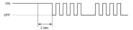
When the system (ECM) enters the diagnostic mode from the normal mode:
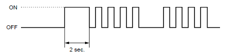
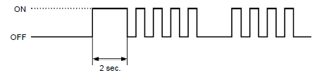
When the system (ECM) enters the diagnostic mode from the registration mode:
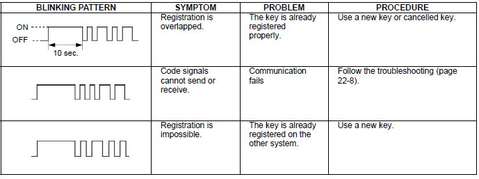
Troubleshooting
The immobilizer indicator comes on for approx. two seconds then it goes off,
when the ignition switch is turned ON with the properly registered key with the
engine stop switch turned ""
and the immobilizer system (HISS) functions normally. If there is any problem or
the properly registered key is not used, the indicator will remain on.
Immobilizer indicator does not operate properly
1. Combination Meter Initial Operation Check
Check the combination meter initial operation.
Is the initial operation displayed?
YES - GO TO STEP 2.
NO - Check the combination meter power/ground line.
2. Serial Communication Inspection
Check the combination meter indication when the serial communication line is abnormal.
Is the indication according to above condition?
YES - Check the serial communication line.
NO - Replace the combination meter, and recheck.
Immobilizer indicator remains on with the ignition switch turned ON
1. Immobilizer Receiver Jamming Inspection
Check that there is any metal obstruction or the other vehicle's transponder key near the immobilizer receiver and key.
Is there any metal obstruction or the other transponder key?
YES - Remove it and recheck.
NO - GO TO STEP 2.
2. First Transponder Key Inspection
Turn the ignition switch ON with the spare transponder key and check the immobilizer indicator.
The indicator should come on for 2 seconds then go off.
Does the indicator go off?
YES - Faulty first transponder key
NO - GO TO STEP 3.
3. Diagnostic Code Inspection
Perform the diagnostic code indication procedure.
Check that the immobilizer indicator comes on then it starts blinking.
Does the indicator blink or stay lit?
BLINKS -Read the diagnostic code.
STAYS LIT -GO TO STEP 4.
4. CKP sensor Line Inspection
Check the CKP sensor lines.
Is there continuity?
YES -
- Open circuit in Yellow wire
- Open circuit in White/yellow wire
NO - Faulty ECM
Diagnostic code  is indicated (Code signals cannot send or receive)
1. Immobilizer Receiver Power Input Line Inspection
Check the immobilizer receiver power input line.
Is the input line normal?
YES - GO TO STEP 2.
NO - Open or short circuit in the Yellow/red wire
2. Immobilizer Receiver Ground Line Inspection
Check the immobilizer receiver ground line.
Is the ground line normal?
YES - GO TO STEP 3.
NO - Open circuit in the Green/yellow and/or Green/orange wire
3. Immobilizer Receiver Signal Line Inspection
Check the immobilizer receiver signal lines.
Are the signal lines normal?
YES - GO TO STEP 4.
NO - Open or short circuit in the Pink wire
4. Immobilizer Receiver Inspection
Replace the immobilizer receiver with a known good one.
Perform the diagnostic code indication procedure.
Is the diagnostic code  indicated?
YES - Replace the ECM with a known good one, and recheck.
NO - Faulty original immobilizer receiver.
ECM
CKP SENSOR LINE INSPECTION
Disconnect the following:
- CKP sensor 2P (Black) connector.
- ECM 33P (Black) and 33P (Gray) connector.
Check for continuity between the CKP sensor 2P (Black) connector [1] and ECM 33P (Black) [2] and 33P (Gray) [3] connector terminals of the wire harness side.
TOOL:
Test probe 07ZAJ-RDJA110
CONNECTION:
Yellow - Yellow
White/yellow - White/yellow
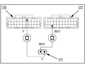
There should be continuity.
Immobilizer receiver
INSPECTION
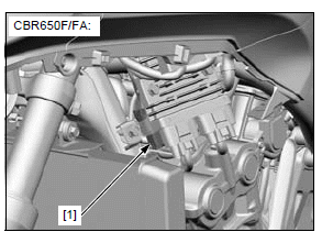
CBR650F/FA:
Remove the left middle cowl.
Remove the immobilizer receiver 4P (Black) connector [1] from the stay and disconnect it.
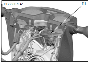
CB650F/FA:
Remove the headlight assembly from the bottom bridge.
Remove the immobilizer receiver 4P (Black) connector [1] from the stay and disconnect it.
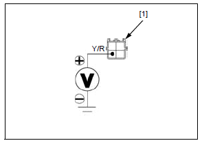
POWER INPUT LINE INSPECTION
Turn the ignition switch ON with the engine stop switch "".
Measure the voltage between the immobilizer receiver 4P (Black) connector [1] terminal of the wire harness side and ground.
CONNECTION: Yellow/red (+) - Ground (-)
There should be approx. 5 V.
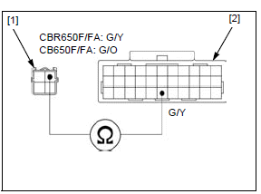
GROUND LINE INSPECTION
Disconnect the ECM 33P (Black) connector.
Check for continuity between the immobilizer receiver 4P (Black) connector [1] terminal and ECM 33P (Black) connector [2] of the wire harness side.
CONNECTION:
CBR650F/FA: Green/yellow - Green/yellow CB650F/FA: Green/orange - Green/yellow
There should be continuity at all times.
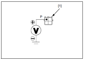
SIGNAL LINE INSPECTION
Turn the ignition switch ON with the engine stop switch "".
Measure the voltage between the immobilizer receiver 4P (Black) connector [1] terminal of the wire harness side and ground.
CONNECTION: Pink (+) - Ground (-)
There should be approx. 5 V.
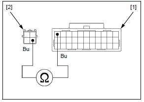
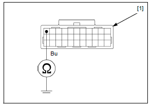
Disconnect the ECM 33P (Gray) connector.
Check for continuity between the ECM 33P (Gray) connector [1] and immobilizer receiver 4P (Black) connector [2] terminals of the wire harness side.
TOOL:
Test probe 07ZAJ-RDJA110
CONNECTION: Blue - Blue
There should be continuity.
Check for continuity between the ECM 33P (Black) connector [1] terminal of the wire harness side and ground.
TOOL:
Test probe 07ZAJ-RDJA110
CONNECTION: Blue - Ground
There should be no continuity.
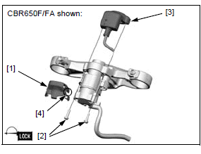
REMOVAL/INSTALLATION
Remove the top bridge.
Remove the following:
- Protector [1]
- Two screws [2]
- Immobilizer receiver [3]
Install the immobilizer receiver in the reverse order of removal.
NOTE:
- Apply locking agent to the screw threads.
- Route the immobilizer receiver wire into the left groove [4] in the protector.
Install the top bridge.
Replacement parts for problem
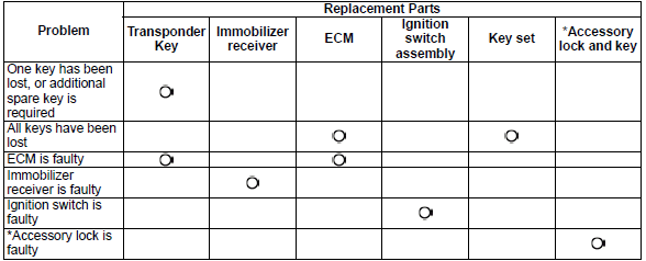
*Accessory lock means the fuel fill cap and seat lock.
See also:
 Honda CBR650 - Service manual > Main/fan control/fuel pump relay
RELAY REMOVAL/INSTALLATION Remove the ABS modulator cover. Turn the ignition switch OFF. Remove the following relays [1] by pulling it up. Main relay [2] Fan control relay [3] Fuel pump relay [4]
 Rider's Manual BMW R 1250 GS GSA
 Owner's Manual Harley-Davidson Sportster XL1200X Forty-Eight
 Owner's Manual Honda CBR650R
 Service manual Honda CBR650
 Owner's Manual Honda PCX125
 Owner's Manual Kawasaki Z1000SX
 Service manual Kawasaki Z1000SX
 Owner's Manual Lexmoto Echo
 Owner's Manual Royal Enfield Interceptor 650
 Service manual Royal Enfield Interceptor 650
 Owner's Manual Yamaha MT-07