 Honda CBR650 - Service manual > Main/fan control/fuel pump relay
RELAY REMOVAL/INSTALLATION
Remove the ABS modulator cover.
Turn the ignition switch OFF.
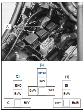
Remove the following relays [1] by pulling it up.
- Main relay [2]
- Fan control relay [3]
- Fuel pump relay [4]
Installation is in the reverse order of removal.
RELAY INSPECTION
NOTE:
- All the relays in the relay box are same parts. The relay function can be checked by exchanging it with a known good one (except main relay) temporarily.
Remove the relay.
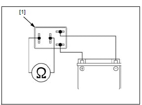
Connect an ohmmeter and a 12 V battery to the relay [1] terminals as shown.
There should be continuity only when 12 V battery is connected.
Fan control relay
CIRCUIT INSPECTION
For relay inspection.
Remove the fan control relay.
RELAY SWITCH/COIL POWER INPUT LINE
Measure the voltage between the relay terminal (switch power input line) of the relay box [1] and ground.
CONNECTION: B (+) - Ground (-)
There should be battery voltage at all times.
If there is no voltage, check the following:
- Red/white wire between the relay box and fuse box 2 for open circuit
- FAN (10 A) fuse
Measure the voltage between the relay terminal (coil power input line) of the relay box [1] and ground.
CONNECTION: D (+) - Ground (-)
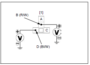
There should be battery voltage when the ignition switch is turned ON with
the engine stop switch " ".
".
If there is no voltage, check the following:
- Black/white wire in the relay box between the main and fan control relays for open circuit
- Main relay and its circuit.
SIGNAL LINE
Disconnect the ECM 33P (Black) connector.
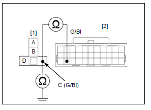
Check for continuity between the relay box [1] and wire harness side ECM 33P (Black) connector [2] terminals.
TOOL:
Test probe 07ZAJ-RDJA110
CONNECTION: C - Green/black
There should be continuity.
If there is continuity, check for open circuit in the Green/ black wire between the relay box and ECM.
Check for continuity between the fuel pump relay terminal of the relay box [1] and ground.
CONNECTION: C - Ground
There should be no continuity.
If there is continuity, check for short circuit in the Green/ black wire between the relay box and ECM.
If all of above inspections are normal, check for open circuit in the Black/blue (A) wire between the relay box and fan motor.
See also:
 Honda CBR650 - Service manual > Turn signal/hazard relay
NOTE: The hazard flasher system can be operated with the ignition switch turned ON. When the ignition switch is turned OFF with the hazard flasher system operating, the system continue operating.
Honda CBR650 - Service manual > Immobilizer system (HISS)
Service information GENERAL When checking the immobilizer system (HISS), follow the steps in the troubleshooting flow chart. Keep the immobilizer key away from the other vehicle's immobilizer key when using it. The jamming of the key code signal may occur and the proper operation of the system will be obstructed. The key has built-in electronic part (transponder). Do not drop and strike the key against a hard material object, and do not leave the key on the dashboard in the car, etc. where the temperature will rise. Do not leave the key in the water for a prolonged time such as by washing the clothes. The ECM as well as the transponder keys must be replaced if all transponder keys have been lost. The system does not function with a duplicated key unless the code is registered into the transponder with the immobilizer system (HISS). The ECM can store up to four key codes (The four keys can be registered). Do not modify the immobilizer system as it can cause the system failure (The engine cannot be started). For ignition system inspection. For ignition switch inspection. For engine stop switch inspection. The following color codes are used throughout this section.
 Rider's Manual BMW R 1250 GS GSA
 Owner's Manual Harley-Davidson Sportster XL1200X Forty-Eight
 Owner's Manual Honda CBR650R
 Service manual Honda CBR650
 Owner's Manual Honda PCX125
 Owner's Manual Kawasaki Z1000SX
 Service manual Kawasaki Z1000SX
 Owner's Manual Lexmoto Echo
 Owner's Manual Royal Enfield Interceptor 650
 Service manual Royal Enfield Interceptor 650
 Owner's Manual Yamaha MT-07