 Royal Enfield Interceptor 650 - Service manual > Journal Bearings Selection Chart
Bearings Selection Procedure
Crankshaft Journal Bearings
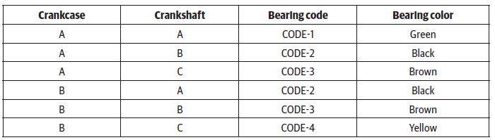
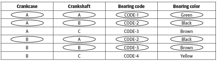
Crankshaft journal bearings selection chart (1.1)
NOTE
- Crankshaft punch mark will be with alphabets A, B, C punch mark only.
- Crankcase punch mark will be with alphabets A, B punch mark only.
Example:
The below sample illustration is only for explanation for selecting crankshaft journal bearing.
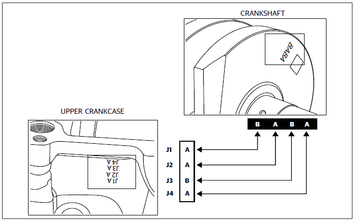
The alphabets punched on the upper crankcase should be correlated with the alphabets punched on the crankshaft web to arrive at the journal wise bearing selection of AA, AB, AC OR BA, BB, BC.
Based on the journal wise markings combination, the corresponding bearing kit (consisting of 2 journal bearings) code/colour should be selected by referring to the chart below as Code - 1, Code - 2, Code - 3, Code - 4.
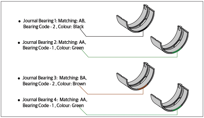
Hence, crankshaft journal bearing selection would be in the following order:
CAUTION Ensure the journal bearing seating areas in the upper and lower crankcases are clean and dry.
Ensure the bearings are correctly positioned and aligned before they are fixed into the crankcases.
Do not interchange the journal bearings, they should be installed in their correct sequential order only.
Do not use any tools while installing bearings as it ma y damage the bearings.
Do not reuse journal bearings once they are removed from the crankcases.
Balancer Shaft Journal Bearings
Balancer shaft journal bearing selection chart (1.2)
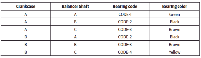
NOTE
- Balancer shaft punch mark will be with alphabets A, B, C punch mark only.
- Crankcase punch mark will be with alphabets A, B punch mark only.
Example:
The below sample illustration is only for explanation for selecting balancer-shaft journal bearing.
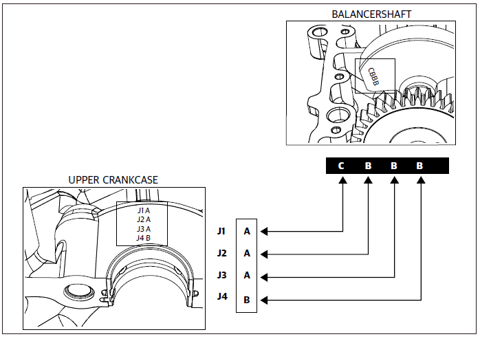
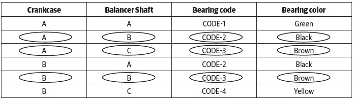
The alphabets punched on the upper crankcase should be correlated with the alphabets punched on the balancer shaft web to arrive at the journal wise bearing selection of AA, AB, AC or BA, BB, BC.
Based on the journal wise markings combination, the corresponding bearing kit (consisting of 2 journal bearings) code/colour should be selected by referring to the chart below as Code - 1, Code - 2, Code - 3, Code - 4.
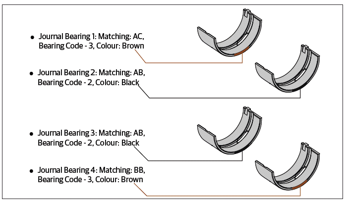
Hence, balancer shaft journal bearing
CAUTION Ensure the journal bearing seating areas in the upper and lower crankcases are clean and dry.
Ensure the bearings are correctly positioned and aligned before they are fixed into the crankcases.
Do not interchange the journal bearings, they should be installed in their correct sequential order only.
Do not use any tools while installing bearings as it may damage the bearings.
Do not reuse journal bearings once they are removed from the crankcases.
Connecting rod journal bearing
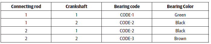
Connecting rod journal bearings selection chart (1.3)
NOTE
- Crankshaft punch mark will be with numerics 1 & 2 only.
- Connecting rod punch mark will be with numerics containing 1 & 2 mark only.
Example:
The below sample illustration is only for explanation for selecting connecting rod journal bearing.
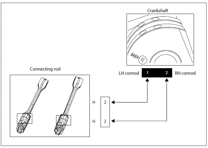
The connecting rod punch mark should be matched with crankshaft numeric punch mark and then the bearing can be selected by referring chart (1.3). Thus the bearing would be Code-2, Code-3
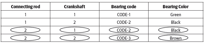
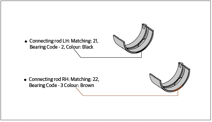
Hence connecting rod bearing would be in the following order
CAUTION Ensure the journal bearing seating areas in the connecting rod and connecting rod cup are clean and dry.
Ensure the bearings are correctly positioned and aligned before they are fixed into the connecting rod and connecting rod cup.
Do not interchange the bearings. They should be installed in their correct order only.
Do not use any tools to install the bearings in the connecting rods/connecting rod cups as it may damage the bearings.
Do not reuse the bearings once they are removed from the connecting rods/connecting rod cups.
See also:
 Royal Enfield Interceptor 650 - Service manual > Clutch Components
Friction plate Inspect the clutch plates visually for uneven wear, seizure and discoloration. Measure the thickness of the friction plate (a) at 4 locations marked by arrows.
 Rider's Manual BMW R 1250 GS GSA
 Owner's Manual Harley-Davidson Sportster XL1200X Forty-Eight
 Owner's Manual Honda CBR650R
 Service manual Honda CBR650
 Owner's Manual Honda PCX125
 Owner's Manual Kawasaki Z1000SX
 Service manual Kawasaki Z1000SX
 Owner's Manual Lexmoto Echo
 Owner's Manual Royal Enfield Interceptor 650
 Service manual Royal Enfield Interceptor 650
 Owner's Manual Yamaha MT-07