 Kawasaki Z1000SX - Service manual > Lighting System
This motorcycle adopt the daylight system and have a headlight relay in the relay box. The headlight does not go on when the ignition switch and the engine stop switch are first turned on. The headlight comes on after the starter button is released and stays on until the ignition switch is turned off. The headlight will go out momentarily whenever the starter button is pressed and come back on when the button is released.
Headlight Beam Horizontal Adjustment
- Refer to the Headlight Aiming Inspection in the Periodic Maintenance chapter.
Headlight Beam Vertical Adjustment
- Refer to the Headlight Aiming Inspection in the Periodic Maintenance chapter.
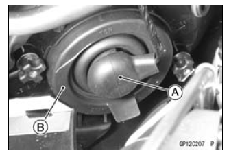
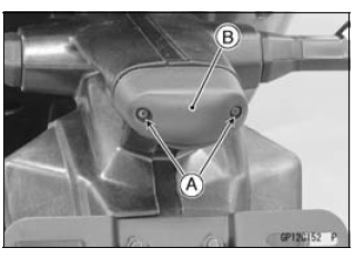
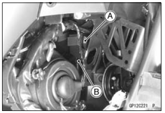
Headlight Bulb Replacement
- Remove:
Meter Cover (see Upper Fairing Removal in the Frame chapter)
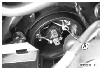
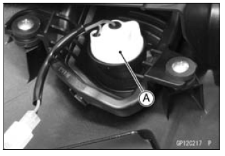
Headlight Lead Connector [A]
Headlight Bulb Dust Cover [B]
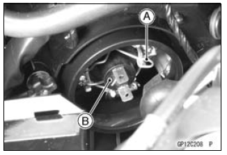
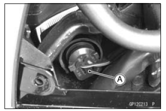
- Remove:
Hook [A]
Headlight Bulb [B]
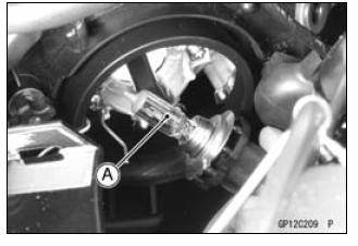
- Replace the headlight bulb.
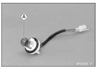
NOTICE When handling the quartz-halogen bulb [A], never touch the glass portion with bare hands. Always use a clean cloth. Oil contamination from hands or dirty rags can reduce bulb life or cause the bulb to explode.
NOTE
- Clean off any contamination that inadvertently gets on the bulb with alcohol or soap and water solution.
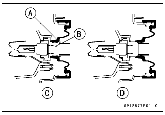
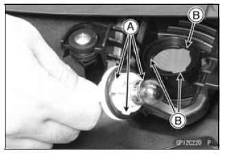
- Fit the projection [A] of the bulb in the hollow [B] of the headlight.
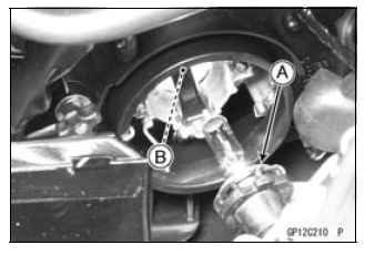
- Install the hook [A].
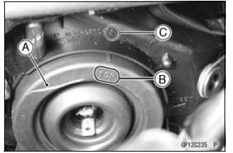
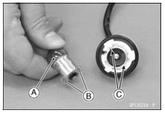
- Fit the dust cover [A] firmly onto the bulb so that the TOP mark [B] is aligned with the arrow mark [C] on the headlight.
- Be sure to fit the dust cover [A] onto the bulb [B] firmly as shown in
the figure.
Good [C]
Bad [D] - After installation, adjust the headlight aim (see Headlight Aiming Inspection in the Periodic Maintenance chapter).
Headlight Removal/Installation
- Remove:
Upper Fairing (see Upper Fairing Removal in the Frame chapter)
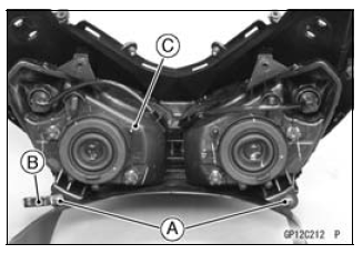
Bolts [A]
Clamp [B]
Headlight Assy [C] - Installation is the reverse of removal.
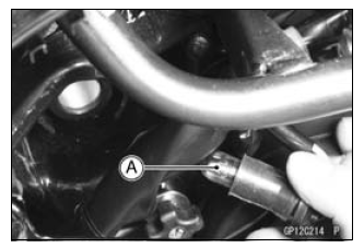
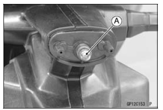
City Light Bulb Replacement
- Remove:
Meter Cover (see Upper Fairing Removal in the Frame chapter) - Pull out the socket [A] and remove it with the bulb.
- Pull out the bulb [A] straight from the socket.
NOTICE Do not turn the bulb. Pull the bulb out to prevent damage to the bulb. Do not use bulb rated for greater wattage then the specified valve.
- Replace the bulb with a new one.
- Install the socket securely.
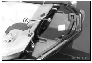
Tail/Brake Light (LED) Removal
- Remove:
Seat Cover (see Seat Cover Removal in the Frame chapter)
Tail/Brake Light Mounting Bolts [A]
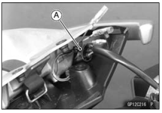
- Disconnect the tail/brake light lead connector [A] to remove the tail/brake light (LED).
Tail/Brake Light (LED) Installation
- Installation is the reverse of removal.
- Tighten the tail/brake light mounting bolts securely.
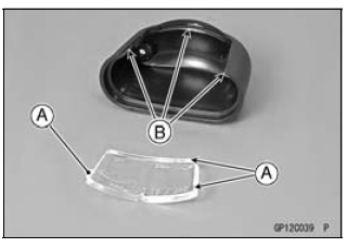
License Plate Light Bulb Replacement
- Remove:
Screws [A]
License Plate Light Cover [B] and Lens
- Pull out the bulb [A].
- Replace the bulb with a new one.
- Insert the new bulb into the socket.
- Fit the projections [A] on the lens to the cover grooves [B].
- Tighten the license plate light cover screws.
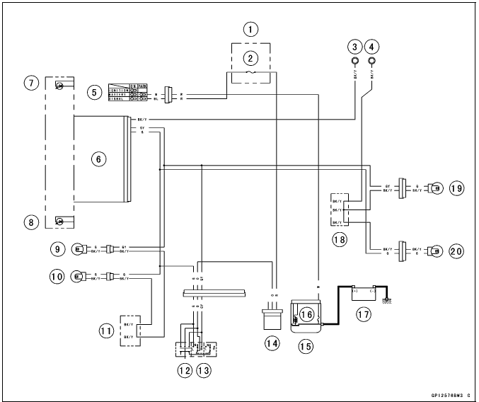
Headlight/Tail Light Circuit
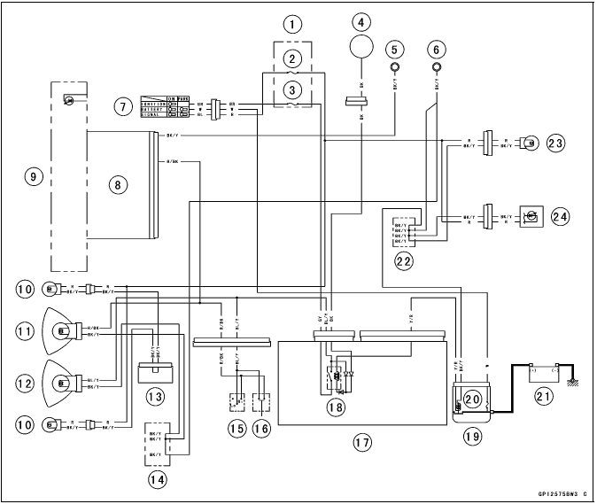
- Fuse Box 2
- Turn Signal Relay Fuse 10 A
- Headlight Fuse 10 A
- Alternator
- Meter Ground
- Frame Ground
- Ignition Switch
- Meter Unit
- High Beam Indicator Light (LED)
- City Light 12 V 5 W
- Headlight (High) 12 V 55 W
- Headlight (Low) 12 V 55 W
- Joint Connector
- Water-proof Joint A
- Dimmer Switch
- Passing Button (Other than US, CA and CAL Models)
- Relay Box
- Headlight Circuit Relay
- Starter Relay
- Main Fuse 30 A
- Battery 12 V 8 Ah
- Water-proof Joint B
- License Plate Light 12 V 5 W
- Tail/Brake Light (LED)
Turn Signal Light Bulb Replacement
Front Turn Signal Light
- Remove:
Lower Fairing (see Lower Fairing Removal in the Frame chapter)
Inner Fairings (see Inner Fairing Removal in the Frame chapter) - Turn the socket [A] counterclockwise and pull out the socket together with the bulb.
- Push and turn the bulb [A] counterclockwise and remove it.
- Insert the new bulb [A] by aligning its upper and lower pins [B] with
the upper and lower grooves [C] in the socket, and turn the bulb clockwise.
- Turn the bulb about 15º.
- Pushing the socket and turn it clockwise.
- Fit the projections [A] of the socket into the grooves [B] of the turn signal light.
- Install the removed parts (see appropriate chapters).
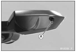
Rear Turn Signal Light
- Unscrew the screw [A] and remove the lens.
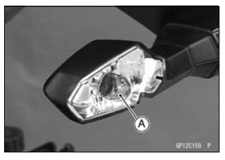
- Push and turn the bulb [A] counterclockwise and remove it.
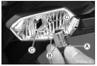
- Insert the new bulb [A] by aligning its upper and lower pins [B] with
the upper and lower grooves [C] in the socket, and turn the bulb clockwise.
- Turn the bulb about 15º.
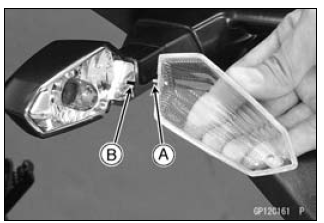
- Fit the projection [A] on the lens to the groove [B] on the socket.
- Tighten the screw.
Turn Signal Relay Inspection
- Remove:
Left Lower Fairing (see Lower Fairing Removal in the Frame chapter) - Pull up the turn signal relay [A].
- Disconnect the turn signal relay connector [B].
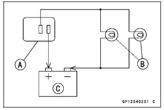
- Connect one 12 V battery and turn signal lights as indicated in the
figure, and count how many times the lights flash for one minute.
Turn Signal Relay [A]
Turn Signal Lights [B]
12 V Battery [C]
If the lights do not flash as specified, replace the turn signal relay.
Testing Turn Signal Relay
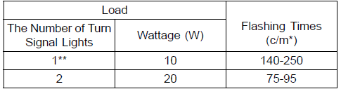
*: Cycle(s) per minute
**: Correspond to "one light burned out"
Turn Signal Light Circuit
- Fuse Box 2
- Turn Signal Relay Fuse 10 A
- Meter Ground
- Frame Ground
- Ignition Switch
- Meter Unit
- Right Turn Signal Indicator Light (LED)
- Left Turn Signal Indicator Light (LED)
- Front Right Turn Signal Light 12 V 21 W
- Front Left Turn Signal Light 12 V 21 W
- Water-proof Joint A
- Hazzard Switch
- Turn Signal Switch
- Turn Signal Relay
- Starter Relay
- Main Fuse 30 A
- Battery 12 V 8 Ah
- Water-proof Joint B
- Rear Right Turn Signal Light 12 V 10 W
- Rear Left Turn Signal Light 12 V 10 W
See also:
 Kawasaki Z1000SX - Service manual > Electric Starter System
Starter Motor Removal NOTICE Do not tap the starter motor shaft or body. Tapping the shaft or body could damage the motor. Drain the coolant (see Coolant Change in the Periodic Maintenance chapter). Remove: Left Lower Fairing (see Lower Fairing Removal in the Frame chapter) Engine Sprocket Cover (see Engine Sprocket Cover Removal in the Final Drive chapter) Harness Holder [A] Loosen the water hose clamp screw [B]. Remove: Water Hose [C] Neutral Switch Connector [D] Water Pipe Bolt [E] Water Pipe [F] Remove the starter motor cable [A] from the cable holder [B]. Remove the mounting bolts [A]. Pull out the starter motor [B] with the cable connected. Slide the rubber cap [A]. Remove the starter motor cable terminal nut [B] and cable.
Kawasaki Z1000SX - Service manual > Air Switching Valve
Air Switching Valve Operation Test Refer to the Air Suction System Damage Inspection in the Periodic Maintenance chapter. Air Switching Valve Unit Test Remove the air switching valve (see Air Switching Valve Removal in the Engine Top End chapter). Set the hand tester [A] to the × 1 Ω range and connect it to the air switching valve terminals as shown in the figure.
 Rider's Manual BMW R 1250 GS GSA
 Owner's Manual Harley-Davidson Sportster XL1200X Forty-Eight
 Owner's Manual Honda CBR650R
 Service manual Honda CBR650
 Owner's Manual Honda PCX125
 Owner's Manual Kawasaki Z1000SX
 Service manual Kawasaki Z1000SX
 Owner's Manual Lexmoto Echo
 Owner's Manual Royal Enfield Interceptor 650
 Service manual Royal Enfield Interceptor 650
 Owner's Manual Yamaha MT-07