 Honda CBR650 - Service manual > Lubrication system
Service information
GENERAL
CAUTION
Used engine oil may cause skin cancer if repeatedly left in contact with the skin for prolonged periods. Although this is unlikely unless you handle used oil on a daily basis, it is still advisable to thoroughly wash your hands with soap and water as soon as possible after handling used oil.
- The oil pump can be serviced with the engine installed in the frame.
- The service procedures in this section must be performed with the engine oil drained.
- When removing and installing the oil pump, use care not to allow dust or dirt to enter the engine.
- If any portion of the oil pump is worn beyond the specified service limits, replace the oil pump as an assembly.
- After the oil pump has been installed, check that there are no oil leaks and that oil pressure is correct.
- For engine oil pressure indicator/EOP switch inspection.
Troubleshooting
Oil level too low
- Oil consumption
- External oil leak
- Worn piston rings
- Improperly installed piston rings
- Worn cylinders
- Worn stem seals
- Worn valve guide
Low oil pressure
- Oil level low
- Clogged oil strainer
- Internal oil leak
- Incorrect oil being used
No oil pressure
- Oil level too low
- Oil pressure relief valve stuck open
- Broken oil pump drive chain
- Broken oil pump drive or driven sprocket
- Damaged oil pump
- Internal oil leak
High oil pressure
- Oil pressure relief valve stuck closed
- Clogged oil filter, gallery or metering orifice
- Incorrect oil being used
Oil contamination
- Oil or filter not changed often enough
- Worn piston rings
Oil emulsification
- Blown cylinder head gasket
- Leaky coolant passage
- Entry of water
Lubrication system diagram

- EXHAUST CAM SHAFT
- INTAKE CAM SHAFT
- PISTON
- CONNECTING ROD
- CRANKSHAFT
- EOP SWITCH
- COUNTERSHAFT
- MAINSHAFT
- OIL COOLER
- OIL ORIFICE
- OIL FILTER CARTRIDGE
- RELIEF VALVE
- OIL STRAINER
- OIL PUMP
Oil pressure inspection
NOTE:
- If the engine oil pressure indicator remains on while the engine is running, check the indicator system before checking the oil pressure.
Remove the EOP switch.
Install the oil pressure gauge attachment [1] to the switch base.
Connect the oil pressure gauge [2] to the oil pressure gauge attachment.
TOOLS:
Oil pressure gauge set 07506-3000001 or equivalent commercially available
Oil pressure gauge attachment 07406-0030000 or equivalent commercially available
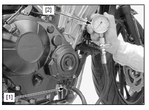
Check the oil level and add the recommended oil if necessary.
Warm the engine to normal operating temperature (approximately 80ºC/176ºF).
STANDARD:
1500 kPa (15.3 kgf/cm2, 218 psi) at 300 min-1 (rpm)
Stop the engine and remove the tools.
Install the EOP switch.
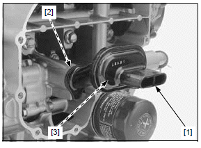
Oil pump
REMOVAL/INSTALLATION
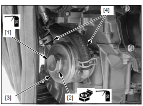
Remove the clutch.
Remove the bolts [1] and oil pump [2].
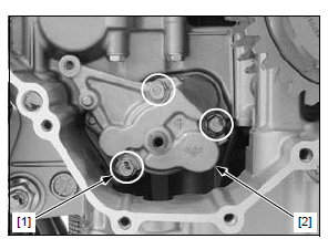
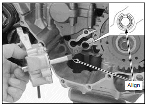
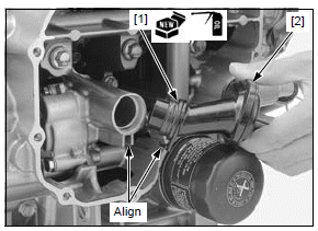
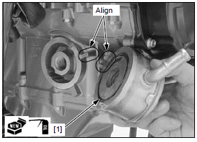
Installation is in the reverse order of removal.
NOTE:
- Align the oil pump shaft end with the water pump shaft groove.
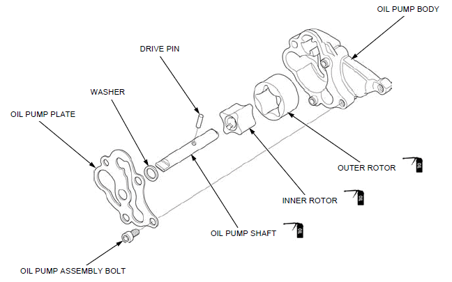
DISASSEMBLY/ASSEMBLY
Disassemble and assemble the oil pump as following illustration.
INSPECTION
- For oil pump drive sprocket, driven sprocket and drive chain inspection.
Inspect the following parts for damage, abnormal wear, deformation or burning.
- Oil pump shaft
- Drive pin
- Inner rotor
- Outer rotor
- Oil pump body
Measure the oil pump clearances according to LUBRICATION SYSTEM SPECIFICATIONS.
If any of the measurement is out of the service limit, replace the oil pump as an assembly.
Pressure relief valve
REMOVAL/INSTALLATION
Remove the oil pump.
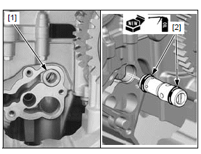
Remove the oil pressure relief valve [1] and O-rings [2].
Apply engine oil to a new O-rings.
Install the O-rings to the oil pressure relief valve grooves.
Install the oil pressure relief valve into the crankcase.
Install the oil pump.
INSPECTION
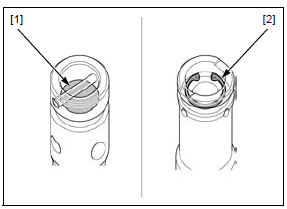
Check the operation of the pressure relief valve by pushing on the piston [1].
Disassemble the pressure relief valve by removing the snap ring [2].
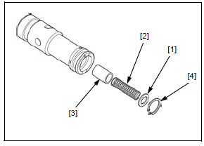
Remove the washer [1], spring [2] and piston [3].
Check the piston for wear, sticking or damage.
Check the spring for fatigue or damage.
Assemble the pressure relief valve in the reverse order of disassembly.
NOTE:
- Install the snap ring [4] with the chamfered edge facing the thrust load side.
- Make sure the snap ring is seated in the groove.
Oil strainer
REMOVAL
Drain the engine oil.
Remove the exhaust pipe/muffler.
Loosen the bolts [1] in a crisscross pattern in 2 or 3 steps and remove the bolts, oil pan [2].
Remove the oil strainer [1] and seal ring [2].
Clean the oil strainer screen [3] and check for damage.
INSTALLATION
Be careful not to damage the mating surfaces.
Clean any gasket material from the mating surfaces of the oil pan.
Apply engine oil to a new seal ring [1] and install it onto the oil strainer [2].
Install the oil strainer into the crankcase while aligning the oil strainer boss with the crankcase groove.
Clean the oil pan mating surface thoroughly.
Apply liquid sealant (TB1207B manufactured by Three Bond or equivalent) to the oil pan mating surface as shown.
- Do not apply more liquid sealant than necessary.
Install the oil pan [1] and bolts [2] to the crankcase.
Tighten the bolts in a crisscross pattern in 2 or 3 steps.
Install the exhaust pipe/muffler.
Fill the engine with the recommended engine oil and check that there are no oil leaks.
Oil cooler
REMOVAL/INSTALLATION
Drain the engine oil.
Drain the coolant from the system.
Remove the bolt [1], sealing washer [2] and oil cooler [3].
Disconnect the oil cooler water hoses [4] from the oil cooler.
Remove the O-ring [1] from the oil cooler.
Installation is in the reverse order of removal.
- Apply engine oil to a new O-ring.
- Align the oil cooler groove with the crankcase boss.
- Apply engine oil to the oil cooler bolt threads and a new sealing washer seating surface.
TORQUE:
Oil cooler bolt: 59 N*m (6.0 kgf*m, 44 lbf*ft)
Fill the crankcase with the recommended oil.
Fill the cooling system and bleed any air.
Check that there is no oil leaks.
See also:
 Honda CBR650 - Service manual > Water pump
MECHANICAL SEAL INSPECTION Remove the under cowl (CBR650F/FA only). Check the bleed hole [1] of the water pump for signs of coolant leakage. A small amount of coolant weeping from the bleed hole is normal. Make sure that there are no continuous coolant leakage [2] from the bleed hole while operating the engine.
 Rider's Manual BMW R 1250 GS GSA
 Owner's Manual Harley-Davidson Sportster XL1200X Forty-Eight
 Owner's Manual Honda CBR650R
 Service manual Honda CBR650
 Owner's Manual Honda PCX125
 Owner's Manual Kawasaki Z1000SX
 Service manual Kawasaki Z1000SX
 Owner's Manual Lexmoto Echo
 Owner's Manual Royal Enfield Interceptor 650
 Service manual Royal Enfield Interceptor 650
 Owner's Manual Yamaha MT-07